
In the main, the only lathes which are still working today are those that were made by: Neumann of Berlin; Scully of Bridgeport Connecticut; and Lyrec of Copenhagen¹.
Not only is an understanding of something about disc-cutting lathes interesting, it helps give a better appreciation of the limits of performance of gramophone (phonograph) records, since the lathe performance and the turntable performance combine to define the fidelity of the reproduction. To that end the performance of a Neumann lathe and cutter-head is given in Appendix 1, and a conclusion section looks at the end-to-end performance of lathe → cutter-head → chisel → stylus → turntable → cartridge.
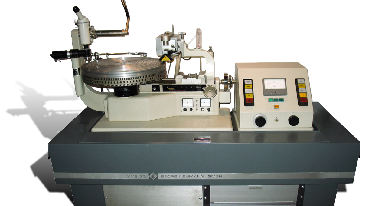
The Neumann lathe design was - more or less - fully mature by 1966 with their VMS 66 lathe. A modified version was released 1970 (the VMS 70 - pictured above) and various innovations was were added in 1980 with the VMS 80 which was their last. Neumann were the only company to offer an entire record cutting system: lathe, cutter-head and electronics. This represented a reduced risk to the customer who was spending a small fortune (more than $100,000 in today's money) and explains the popularity of Neumann equipment.
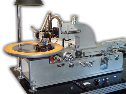
Scully lathes are often fitted with Westrex cutter-head and electronics. The history of Westrex goes back to the very dawn of electrically recorded records.
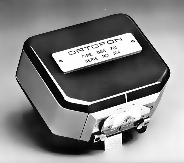
Founded in Copenhagen, Ortofon initially developed a synchronized sound system for film. In 1946 Ortofon developed its first moving coil cutter-head.
The following is intended to be a general survey of all recording lathes. It refers often to the Neumann VMS 70 because this was - and still is - the world's most popular recording lathe. Where other designs differ greatly from the Neumann philosophy, this is highlighted.
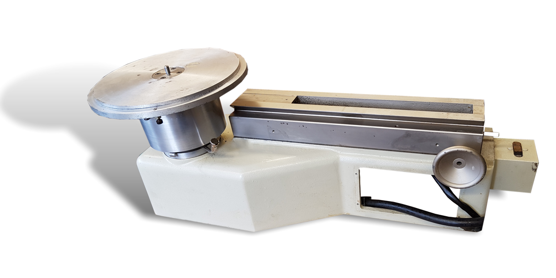
The basic Neumann lathe-bed (left) is built up on a heavy cast-iron base which remained virtually unchanged from the nineteen-thirties until Neumann stopped making record lathes fifty years later¹. Like a metalworker's lathe, the record lathe has a turning spindle driven by an electric motor; although, in the case of the record-lathe the work spins horizontally. The tail-stock of the lathe is a bracket which runs on the bed of the lathe on a slide. In the case of the Neumann the bracket is quite slender and is sometimes called the "swan-neck" bracket. In a Scully lathe, the bracket is more massive. The cutter-head is mounted on the bracket which runs on the slide, driven by the lead screw.
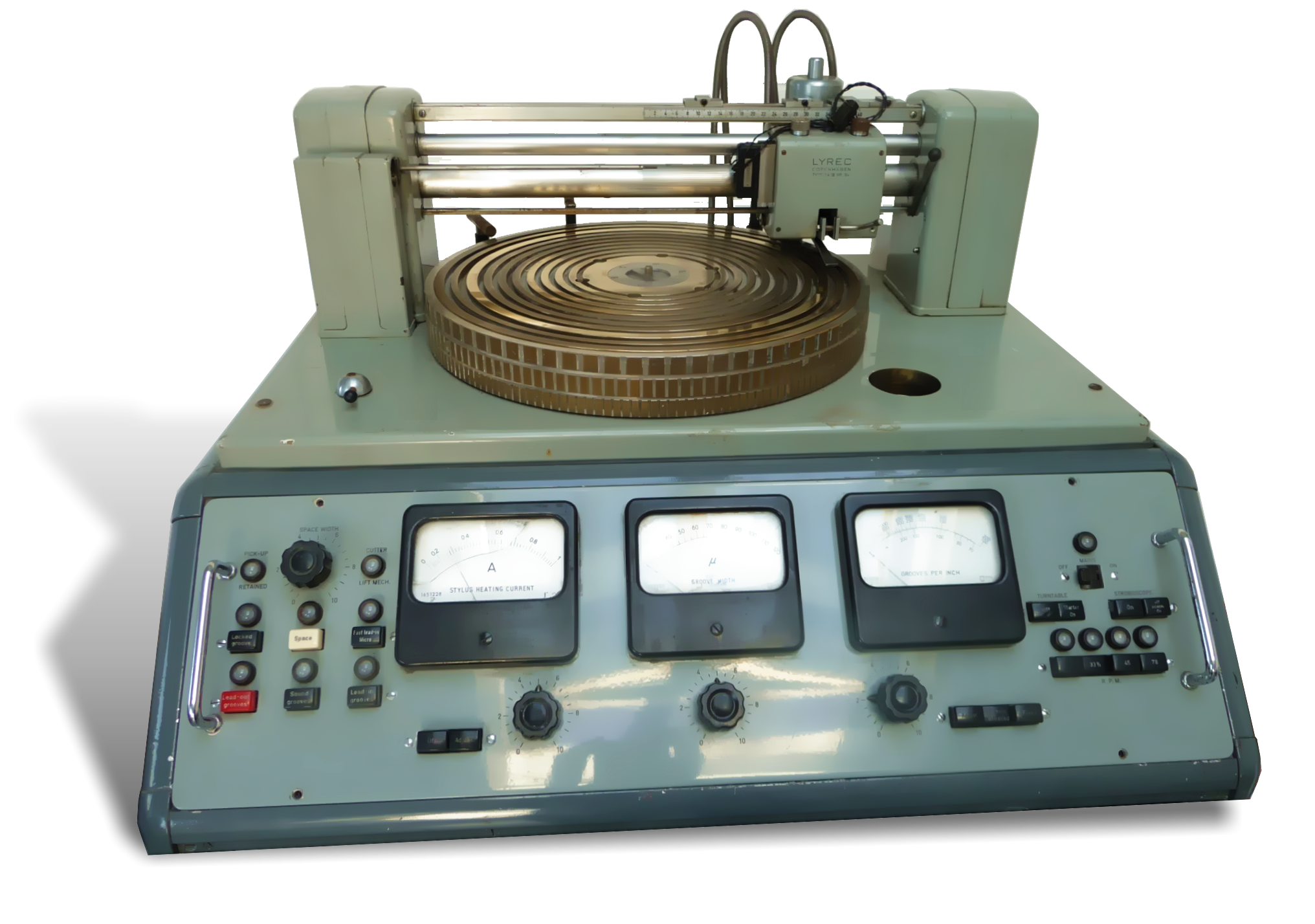
The Lyrec lathe is a more compact device that either the Neumann or the Scully in which the cutter-head runs on rails behind the work. As a consequence, Lyrec lathes look less like something adapted from the metal workshop.
In the case of the Neumann lathes, the turntable itself is of heavy cast-iron and weighs 30kg. Lyrec lathes too used a heavy, machined, brass turntable. The turntable on a Scully lathe is less massive, instead it is coupled via a resiliant coupling to a shaft which carries a heavy flywheel driven via a belt from the motor.
 The single, or three-phase, synchronous turntable motor which drives both the Lyrec and Neumann lathes was manufactured by Lyrec. The motor is very unusual in that the motor RPM is equal to disk RPM - a very slow-turning synchronous motor. No gear-train or belt is used to step-down a smaller, fast turning motor as we see in domestic turntables. These lathe are thus direct-drive.
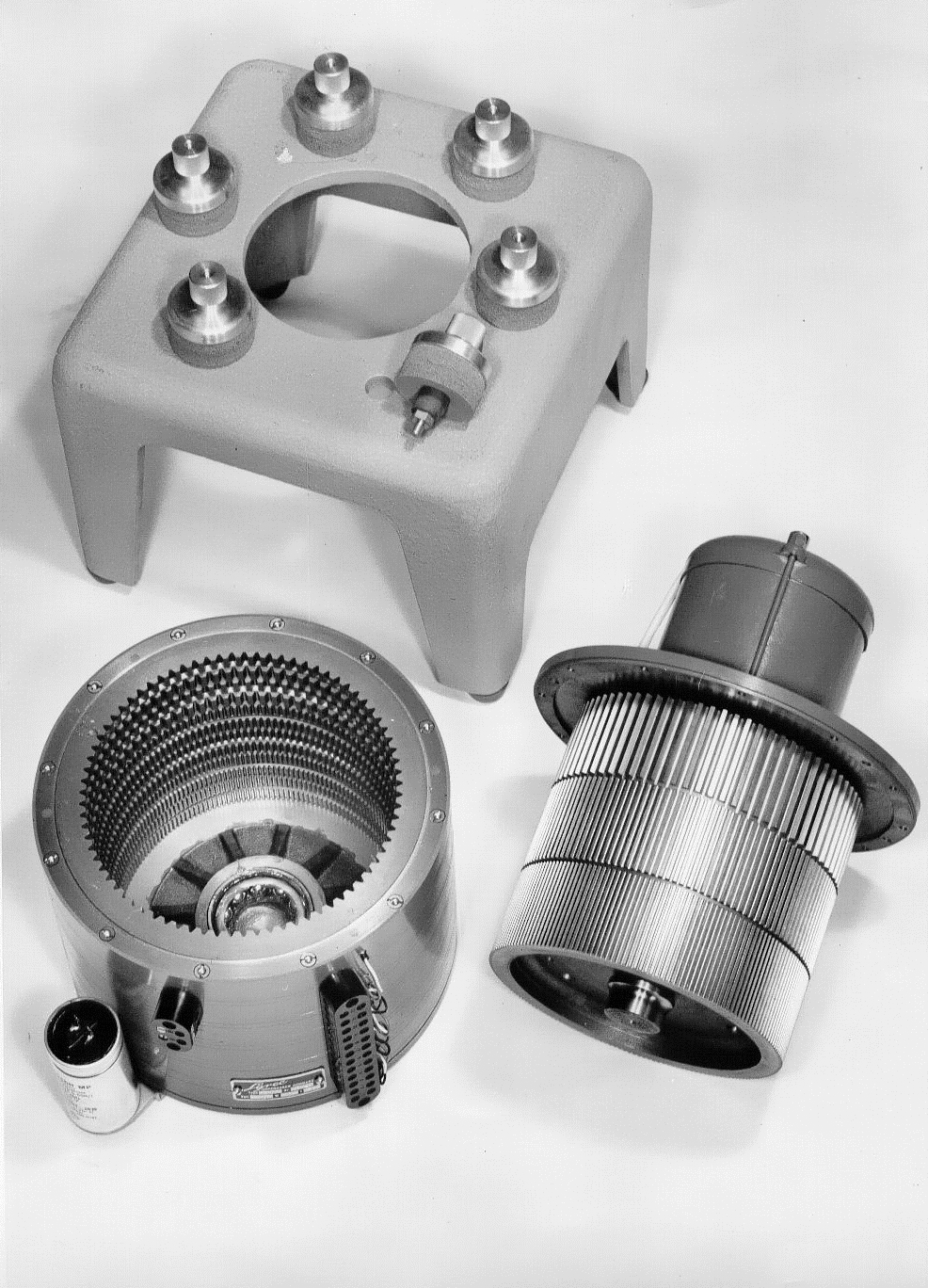
From the equation given on this page which has an introduction to electric motors, this implies the motor must have 90 pairs of poles to turn at 33⅓ RPM on 50Hz AC current (and 108 pole-pairs to run on 60Hz AC current) which demonstrates what an unusual piece of equipment this Lyrec motor is (see left). Neumann adopted SP-02 crystal-locked, DC motors made by Technics after 1976¹.
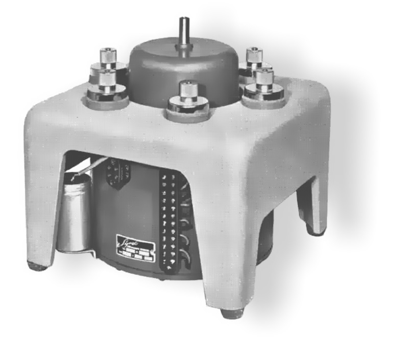
In both the Lyrec and the Neumann lathes, the motor is positioned under the lathe turntable in a housing which sits the floor (right). In this way, vibration from the motor body is isolated from the lathe frame and bed. In the Neumann lathes, the motor drive is connected to the turntable by a connecting rod with two simple rubber disk couplings. These couplings go some way to decouple motor vibration from the turntable, but would be wholly inadequate for high-quality.
To realise the degree of isolation required, the turntable is driven by a hydrokinetic coupling which works a little like an hydraulic clutch. The motor drives the outer cylinder of the coupling which is a cup filled with half a litre of oil. This is the primary turbine. The turntable is driven from a second inverted cup (the secondary turbine) which is submerged in the turning oil-bath. Once the turntable is up to speed and the two parts have identical angular velocities, there is no net centripetal force and the motion of the fluid is circular and co-axial with the axis of rotation. The turntable is thus coupled to the motor solely by a thin layer of oil between the walls of two concentric cylinders. This arrangement, together with the massive turntable, almost completely eliminates rumble and flutter from being transmitted from the motor to the turntable.
In the Neumann, a vacuum-chuck sits on top of the basic, cast-iron turntable and provides vacuum hold-down for all sizes of blank lacquers. The surface of the chuck is the turntable of perforated aluminium which is visible to the user (see picture below). A vacuum, provided by a small motor, ensures that the lacquer is held flat and cannot slip on the turntable. The common method of creating the vacuum is by means of a small pump driven by an electric motor. In the Neumann lathes, the pipe from the vacuum pump is often connected to the hollow centre pin of the turntable chuck with a loose fitting adapter. A similar vacuum-chuck is used in the Lyrec - although the pipe from the vacuum pump is connected underneath the turntable as it is on later Neumanns. Scully lathes for years simply relied on a cork mat to stop the lacquer slipping. Scully lathes in modern use often have a customised vacuum-chuck fitted.
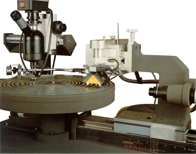
The lathe bed on the Neumann and Scully lathes is of the slide type (clearly visible in the picture of the Neumann VMS 80, left). The sled which runs on the slide and to which the bracket is attached which carries the weight of the cutter-head runs on ball bearings. The Lyrec lathe is more compact with the cutter-head running on rails behind the turning disc. (This was a feature of other, older lathe designs by manufacturers such as Presto of Paramus New Jersey). By this means, the lead screw drive is much nearer the cutter-head pivot than is the case with either the Neumann or the Scully where the drive is made at the other end of a bracket which can pivot minutely. This is an advantage of the Lyrec lathe.
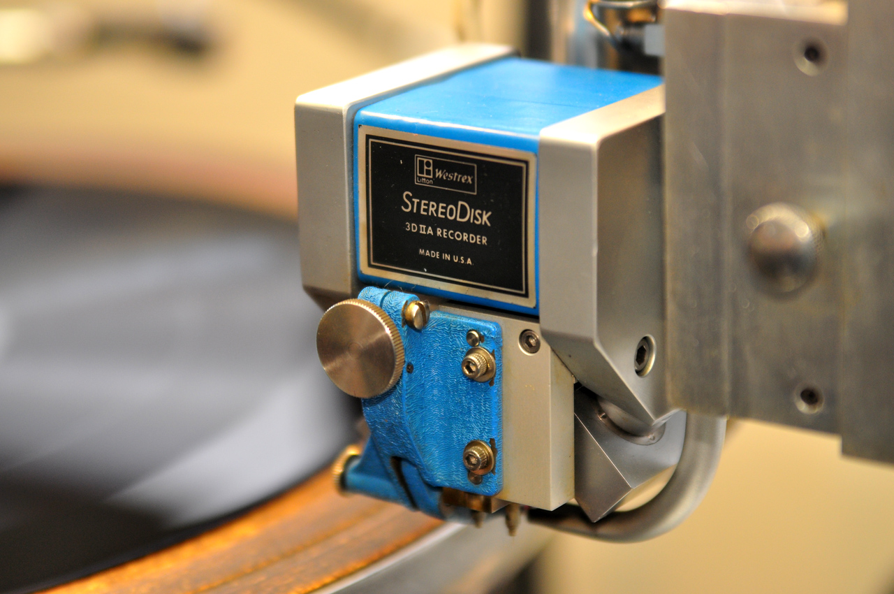
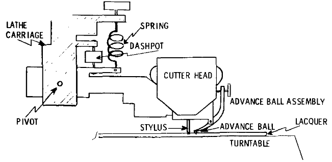
The bracket suspends the cutting head above the rotating lacquer disc permitting the stylus to groove the disc. The penetration of the stylus into the lacquer must be very accurately controlled to avoid added and unwanted vertical modulation of the signal. In the case of the Westrex (illustrated below)², almost all the weight of the pivoting cutter is counterbalanced by a damped spring. In the Neumann, the cutter-head is also mounted on a spring counterbalance but is assisted by a damped electrodynamic moving-coil suspension which is controlled on the depth-of-cut control panel.
This control panel sits in an aperture in the lathe-bed casting, just below the slide. It is clearly visible in the picture of the VMS 70 at the top of this page. This control panel supplies a DC current to the moving-coil system suspension which acts against cutter-head's weight. By adjusting a potentiometer to control the standing current in this moving-coil system, cutting depth may be controlled - the current being displayed on a moving-coil meter. An installed microscope is used to make the depth of cut adjustment. In later VMS 80 lathes, a television camera is attached to the microscope so that the groove may be observed on a TV monitor.
The depth of cut is deepened during lead-in, lead out and final groove. This is to ensure that the playback stylus settles firmly in these grooves for tonearn set-down and pick-up. (Remember that a groove made with a V-shaped cutter also gets wider, the deeper it is.) There is a further rotary control and moving-coil meter on the depth control panel to make these adjustments.
If the lacquer disc has surface irregularities (warp), the pressed vinyl record will contain these irregularities as unwanted modulation. The Westrex cutter uses a sapphire hemisphere known as an advance ball which rides on the lacquer disc and mechanically transmits surface irregularities to the cutter-head. This reduces the unwanted groove modulation because the cutter follows the warp. As a result, quiet grooves can be cut with almost constant depth even if the lacquer surface is not flat. The ball is positioned precisely in front of the stylus so that any marking of the lacquer is removed when the stylus cuts the groove.
 The cutter-head energises the cutting stylus which engraves the record groove in the lacquer. A stereo cutter-head is constructed very like a miniature pair of loudspeakers. The stylus is mechanically coupled to a pair of moving-coils through which the left- and right-channel signal currents flow whilst sitting within field of a powerful magnet.
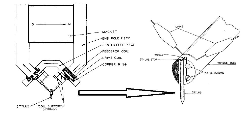
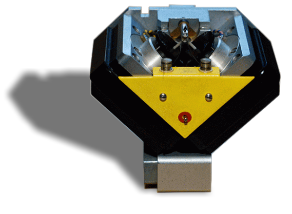
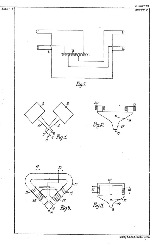
The way in which the two coils control the stylus differs between brands of cutter-heads. In the case of the Westrex and the Neumann cutter-heads, the principle as as illustrated (left)³. Two orthogonal solenoids, each mounted 45° to the horizontal are coupled to a tube at the end of which is secured the stylus (about which more later). This tube is arranged to twist and is known as the torque tube. In this way, the entirely linear, separate motion in the two solenoids is converted into a composite movement for engraving both walls of the disc. The mechanism is clearly visible in the Neumann cutter-head (below right).
 The Ortofon stereo cutter-head is arranged so that two, vertical coils actuate a rocking bridge. The manner in which the left and right signals are resolved into two 45° movements is less easy to envisage with this arrangement. But the result is the same. Incredibly, both methods were anticipated by Blumlein in his stereo patent of 1932 written 30 years before the first stereo record was produced.
The small coils in the cutter-head are driven from large amplifiers (see below). Because of this, the extreme heating of these coils is possible even to the degree of fusing of the fine-gauge winding wire. To extend with working envelope of the cutter-heads, some cutter-heads are sealed by the manufacturer to allow helium gas to be injected into the gaps between the pole pieces and the coils. Low density gases, such as hydrogen and helium have a higher thermal conductivity than normal air and thus carry the unwanted heat away from the coils to the mass of the pole pieces more quickly.
Constant-velocity
As we have seen, the each channel of the cutter-head is a moving-coil device which works in a similar way to a loudspeaker. Just as with a loudspeaker, it is the bass frequencies which cause the cutter to move the most: the high frequencies cause it to move only very slightly. (If you've ever looked at a loudspeaker cone as it reproduces music you'll recognise this.)
Thus, if the record cutter-head is fed a signal with has a constant amplitude with respect to frequency (a signal with a flat frequency-response), the cutter will respond to this signal so that, as the frequency increases, and the slope of the signals steepen, the amplitude of the groove inscribed on the disc will fall. We say that the cutter-head has a constant-velocity characteristic.
The problem with a constant velocity characteristic is that the bass frequencies modulations engraved on the disc would be enormous and cause the wall of the groove to break down, and the high-frequencies so tiny that they would be swamped in noise due to the physical roughness of the groove. So, cutter-heads are not fed with a signal with a flat frequency-response characteristic as explained in detail on this page. Modern records are recorded with a transfer characteristic which reduces the bass frequencies, so as to limit stylus excursion, and boosts high-frequency, to improve the signal-to-noise ratio of the medium.
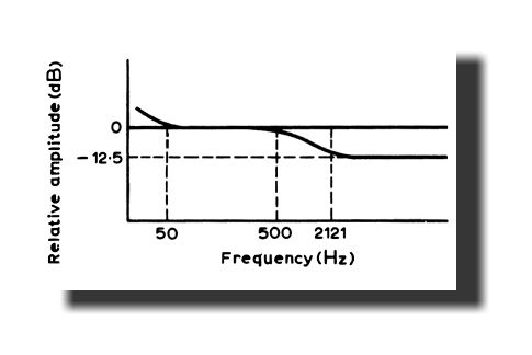
The signal actually engraved in the groove of a modern record when recorded according to the RIAA standard, has a frequency characteristic which has two broad regions of constant-amplitude (as opposed to constant-velocity) separated by a step, as illustrated right. The first region of the constant-amplitude cut is due to the turnover filter in the recording equaliser. This cuts bass frequencies and thereby forces a rising electrical response through the bass-middle frequencies. This complements the falling response of the cutter-head. The second region is due to pre-emphasis, where once again, the rising electrical response complements the falling-response of the cutter. The shelf is caused by the flat part of the recording characteristic (in RIAA, between 500Hz and 2121Hz) where there is no compensation for the falling response of the cutter-head.
 Saying that the final cutter-head has a constant-velocity characteristic is true, but it is only realised by a system to stabilise the transfer-function of the transducer.
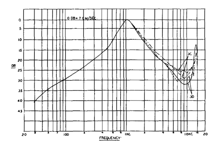
If you imagine taking a small loudspeaker and replacing the paper cone with a small aluminium tube in torsion, you would intuitively imagine that the sound produced would be very shrill and "tinny" (and not very loud!). A moving-coil loudspeaker is arranged so that its fundamental resonance is below its lowest useful frequency. That's possible because the support spider can be made very compliant. Not so the moving-coil cutter-head where, because the torque bar is stiff, the main resonance is right in the middle of the audio range; about 1 - 2 kHz. Without remedial engineering, the cutter-head would produce a truly awful sounding record. The uncompensated frequency-response of the Westrex 3C and 3D cutter-head is given in the illustration (left)³.
The remedy is negative feedback which is derived from the movement of the actuating coils by two further feedback windings shown in the illustration of the principle of the cutter-head above. These coils sense the velocity of the solenoid deflection and generate a signal which is fed back to the cutting amplifier where it is subtracted from the incoming signal to compensate for the uneven frequency response of the transducer. With careful mechanical and electrical design, a very considerable negative-feedback fraction is applied and this has the effect of linearising the response except for a gentle fall at low-frequencies and some high-frequency irregularities. These may be addressed by simple passive equalisation networks and may even be absorbed in the inverse RIAA equalisation.
The feedback signals from the lower coils play a further rôle in being the last point in the audio chain where a monitoring signal may be derived.
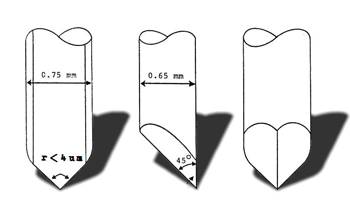
The mineral corundum (Al2O3) is normally used for the cutting chisel in the form of synthetic ruby or sapphire. Blue sapphire is usually considered the best material for the record-cutting as these gems may be manufactured without grains or impurities and can by shaped very precisely; with clean, sharp edges. The dimensions of the sapphire stylus in an Ortofon lathe are illustrated. Note the radius of the tip of the stylus (less than 4µm).
The advantages of hot-stylus recording have been known since the 1890s. The ability to cut clean grooves with sharp-edged styli is greatly eased if the stylus is hot. The groove-noise of an LP groove reduces by almost an order of magnitude when the heat is provided and the improvement in frequency response is marked.
Stylus heating facilities consist of two small terminals on the cutter-head to which may be attached a simple heater coil energised from an AC source. The heater coils are made using fine-gauge enamelled resistance-wire so that about 7½ turns of wire surround the sapphire stylus.
As the groove is cut, the lacquer removed, known as swarf, must be continually cleared away from the stylus and the disc surface. The swarf is removed by positioning a suction tube close to the stylus tip. The vacuum for the suction is usually obtained from the same pump that provides vacuum to the turntable chuck. The swarf is fed into a container that has to be emptied periodically.
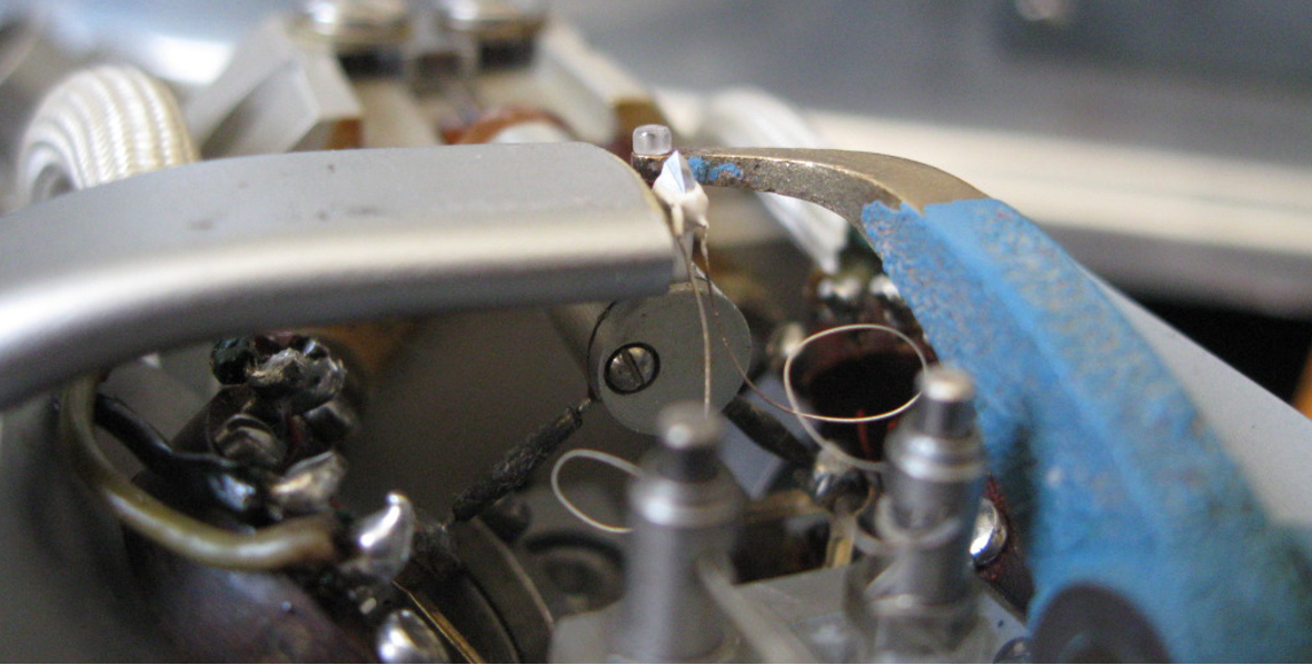
The close-up picture of a Westrex cutting head nicely illustrates the swarf removal pipe, the heated stylus and its connections as well as the cutting stylus and the advance ball.
 In the Neumann lathes, the pitch control console is a separate piece of equipment which is situated next to the lathe bed to its right. (Note that pitch here means the number of grooves cut per inch, that's to say like the pitch of a thread, rather than musical pitch.) Unlike in a metalworker's lathe, no power or drive is taken from the turntable motor to drive the lead screw; the pitch drive is entirely self-contained and has its own electric motor. The pitch control unit is coupled to the lead screw by a resilient coupling.
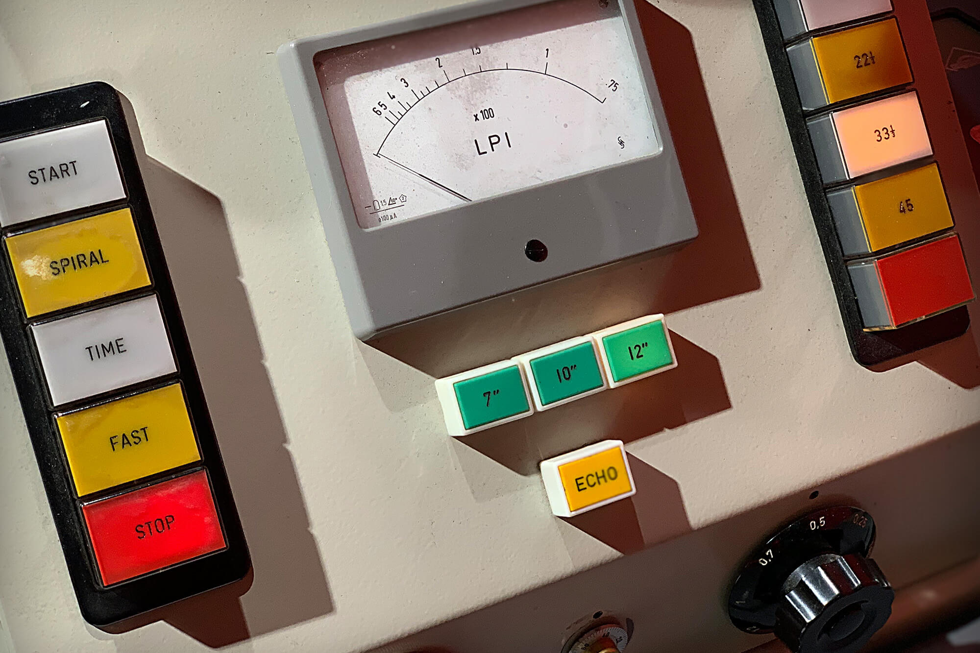
The pitch control console of the VMS 70 (right) has several control push buttons to stop and start the lead screw motor and control its speed and hence the pitch of the spiral engraved on the lacquer. A dial is provided, calibrated by a meter in lines per inch (LPI), which allows the basic pitch of the grooves to be set. Buttons are provided to speed-up the drive motor for the lead-in and lead-out and for the inter-track spaces. A button labelled rather confusingly "ECHO" allows the pitch to be widened to prevent pre-echo print-through from a loud groove to a quiet one.
Cutter preamplifiers
In the VMS 66 and 70, the cutter preamplifiers are known as the SE66 recording equaliser and the SAB-74B equaliser respectively. Jump to a page which analyses the circuits of these equalisers.
Cutter-head power amplifiers
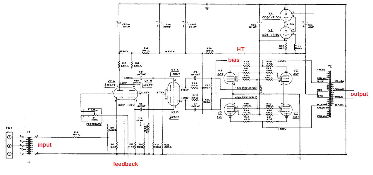
The accelerations required to drive the cutter-chisel are immense, and the amplifiers for cutting records were the height of audio engineering during the heyday of gramophone records. The Westrex RA-1574-B amplifier is illustrated³. It uses parallel pairs of 807 beam-tetrode tubes with fixed-bias to generate 75 watts RMS. Note how the signal and negative feedback from the cutter-head are combined in the first valve (tube). This is one area where tube technology continued beyond its swan song in consumer equipment, although by the end of the 1960s, most new cutting amplifiers were solid-state.
The term efficient space utilisation was widely used in the heyday of record cutting. It referred to the efficient use of the record surface to maximise the playing time of the record. A phonograph record is an entirely mechanical form of memory. Soft sounds only require small groove deflections to capture them and the grooves may be closely packed together. This allows for more spirals of groove and a record with a longer playing time. Loud sounds, on the other hand, create greater groove modulation and thereby the requisite need to increase the pitch between the grooves and a reduction in playing time.
With skilful manual control of the lead screw, it would be possible, by taking careful notes and using a stop-watch, intelligently to adapt the groove pitch so that it was narrow for the quiet periods of music and wide for the loud episodes. In the case of a constant-speed motor-driven lead screw, the only option would be to set the pitch for the worst-case requirement and put up with the poor space utilisation of the disc in the quiet movements; an unpopular compromise. What was needed was an intelligent system which could anticipate and adapt the groove pitch based on the musical content. It is these two features of anticipation and intelligence which justify the term computer controlled lathe which came to be used well before digital computers became a part of everyday life.
Neumann's VMS 66 lathe, released in 1966 was described as computer controlled although it contains nothing which resembles a modern computer in its electronics. In this case, the computer is an analogue computer.
Pitch control
The pitch control system requires an advanced feed of the audio. It is no use trying to widen the pitch of the grooves when the musical crescendo arrives. By that time, it's too late! The change in pitch is effected by controlling the lead screw motor with a signal derived from an added magnetic tape-head spaced about 38cm (≈ 1 second) ahead of the normal reproduce head in the tape machine supplying stereo signals to the disc recorder.
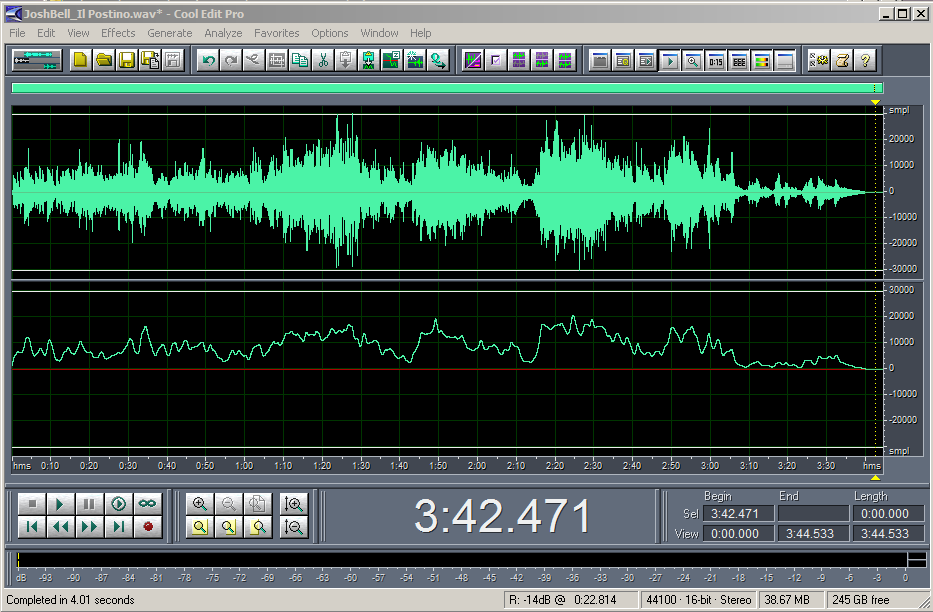
Following summation, equalisation, amplification and rectification, the incoming signal from the advanced playback head is a measure for the space required to record the modulation signal. This control signal is added to the steady current programmed by the lathe operator on the the pitch control console. The control signal for the pitch-control is shown as one channel of an audio signal in the screen capture from the DAW (right).
Depth control
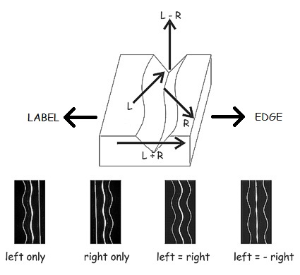
Neumann realised that even greater space utilisation could be accomplished if groove depth (as well as pitch) could be controlled dynamically. Depth modulation of the groove is dependent on channel difference as the diagram (right) illustrates.
They reasoned that, just as the time-advanced left + right signal could be processed to predict the required groove pitch, the time-advanced left - right signal could be used to predict required depth.
Remember two things:
We have seen how depth actually affects pitch and that is the gain of depth control. There is a flip-side: when more depth is required, the pitch must be made coarser. To that end, the depth control controller produces an output which acts as another input to the pitch controller.
It's easy to see, with this degree of sophistication, that the term computer is justified.
As advances in large-scale integration of electronics and computer technology were made throughout the last fifteen years of the LP era, computer control became more intelligent still so that even better space utilisation was obtained.
 The cutting engineer's task is to maximise the amplitude of the "wiggles" which are the data in the mechanical memory of the medium. We want that data to be as far above the groove noise as possible without either damaging the medium, or the recording cutter-head, or the recording stylus. It's a tightrope walk and it's a job made much harder by signals of certain characteristics. Amongst these are:
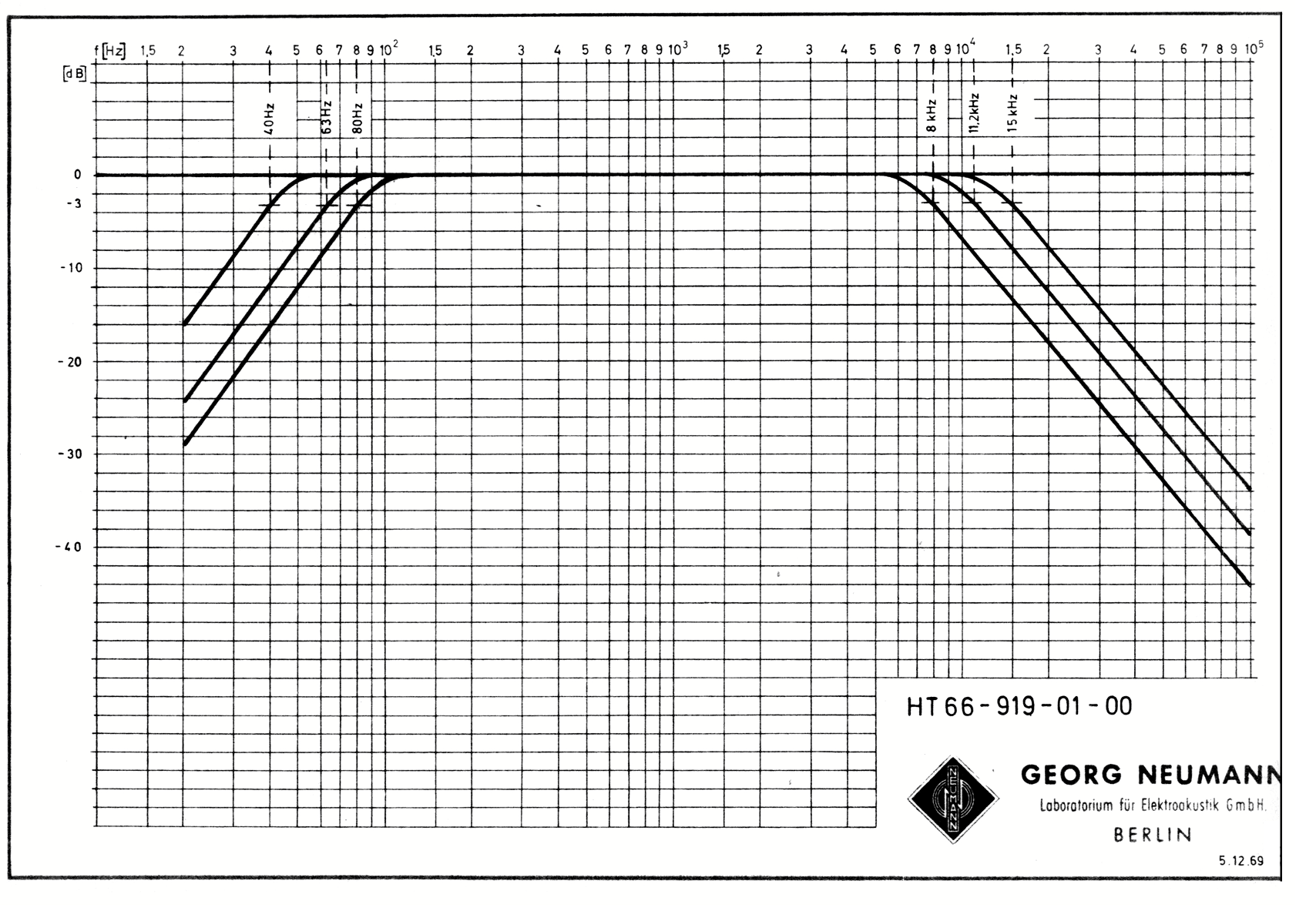
Now, the cutting engineer is well aware of these issues and has special equipment to deal with these signals when present: like steep-cut filters for the extreme bass and treble. Curves which illustrate the high-pass and low-pass filters in the VMS 66/70 are illustrated. Low-pass filters allow the engineer to control cutting stylus velocity within acceptable limits. And the lathe electronics rack contains acceleration limits or de-essers which impose limitations on the acceleration of the cutting stylus.
The engineer also has an Elliptical Equaliser, a piece of equipment somewhat surrounded in mystery.
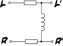
Neumann's legendary Elliptical equaliser. Just three impedances, but very cunning!
The falling reactance of the inductor forces lower frequencies to mono so that bass is recorded onto a record as lateral modulation only
In fact, the Elliptical equaliser (Neumann EE66 or EE70) is a relatively simple device, the heart of which is just three impedances. These impedances interact so that the equaliser introduces crosstalk in the bass frequencies to force them to be mono. This reduces the out-of-phase part of the signal and limits the amplitude of the vertical groove modulation.
† Used for half-speed mastering of 45s.
1. Mastering for Records, the methods and problems Batchelor, T. Snugglebugs eBooks Denmark 2016
2. Lacquer warp, Advance ball, and Disc cutter dynamics Gravereaux D.W., AND White, J. Presented at the 52nd Convention of the Audio Engineering Society, New York. October 1975.
3. The Westrex 3D StereoDisk System, Nelson C.S. and Stafford J.W. Journal of the Audio Engineering Society Volume 12, Number 3 July 1964.
4. An electronic forward drive in transcription turntables. Hirsch F.H. (Thorens-Franz AG Wettingen, Switzerland) Presented at the 37th JAES Convention October 13-16, 1969
5.  Records are a highly-standardised mechanical-medium, it is therefore posible to calculate the dynamic range.
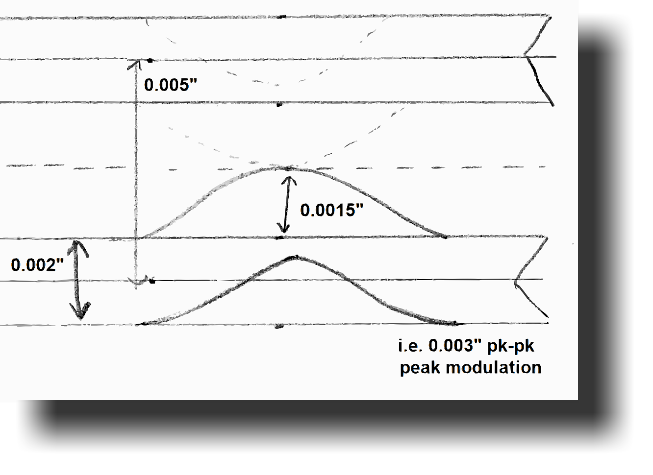
The standardised groove geometry on an LP record is of a 2 thou* groove on a 5 thou spacing (the latter being based on 200 grooves per inch). As the diagram right illustrates, the absolute maximum modulation of a groove is ±1.5 thou which is equivalent to 76µm pk-pk modulation.
At the other end of the scale, the surface roughness of an LP is about 25nm, this being about 1/20th the wavelength of light. So calculating we can say,
76µm/25nm = 3040 = 69dB
This is happily very close to the figure derived from measurement, the latter being inevitably a little higher due to mechanical noise in the tuntable bearings and electrical noise in the cartridge and preamplifier. So we can be very confident of this figure. We can say that an LP record is roughly equivalent to a correctly dithered 13 bit-resolution digital-medium.
* Thousandths of an inch, equivalent to the American term "mil" and equal to 25.4 µm.
6. The internal resistance of a typical moving-coil phono cartridge is 10 ohms. The maximum RMS output from the cartridge is about 5mV (that being 20dB above the nominal 0.5mV @ 5cm/s level).
The RMS thermal noise generated in 10Ω in a bandwidth of 20kHz is 57nV. So the ratio between maximum signal and noise voltage is,
5mV/57nV = 87,720 = 99dB.
This is very substantially (28 times!) better then than the theoretical maximum from the vinyl medium. The preamplifier will probably reduce this margin by 6dB but clearly the electronics are comfortably better than the mechanical limitations of the medium itself.
A similar figure for dynamic-range is possible from a moving-magnet type provided that the inductive nature of the cartridge is isolated (as it is in the PHLUX cartridge.) Here, the internal generator resistance is 100 times higher but, because of the square-root sign in the calculation for thermal noise, the noise is only 10 times higher. The output voltage is also about 10 times higher too, so the ratio of maximum-signal to noise is maintained.
Pspatial Audio Home page
For all support issues, go here.
For Pspatial Audio sales, email: sales@pspatialaudio.com
