
What's a turntable?
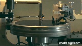
As the original, completely smooth, lacquer disc turns in the recording studio, sound signals are engraved as modulations (“wiggles”) in a spiral groove. On replay, the turntable's job is to trace these modulations in a manufactured copy of the lacquer disc. It does this by rotating the disc at a constant speed with a motor and allowing a needle (or stylus) fixed at the end of a freely pivoting tonearm to follow the groove wiggles.
The stylus traces the grooves and is arranged to move a magnet and a coil relative to one another. A very small voltage is thus generated which is subsequently amplified and used to drive a loudspeaker.
The illustration below summarises the three methods used to couple the turntable platter to the driving electric motor. The picture is also a historical narrative in that the three types of propulsion each had their place in the development of record players.
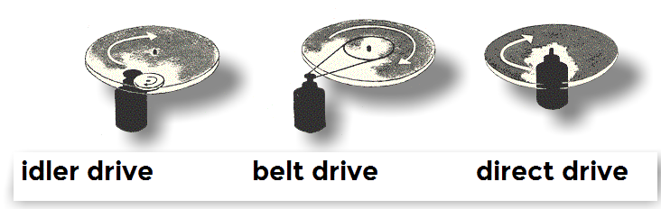
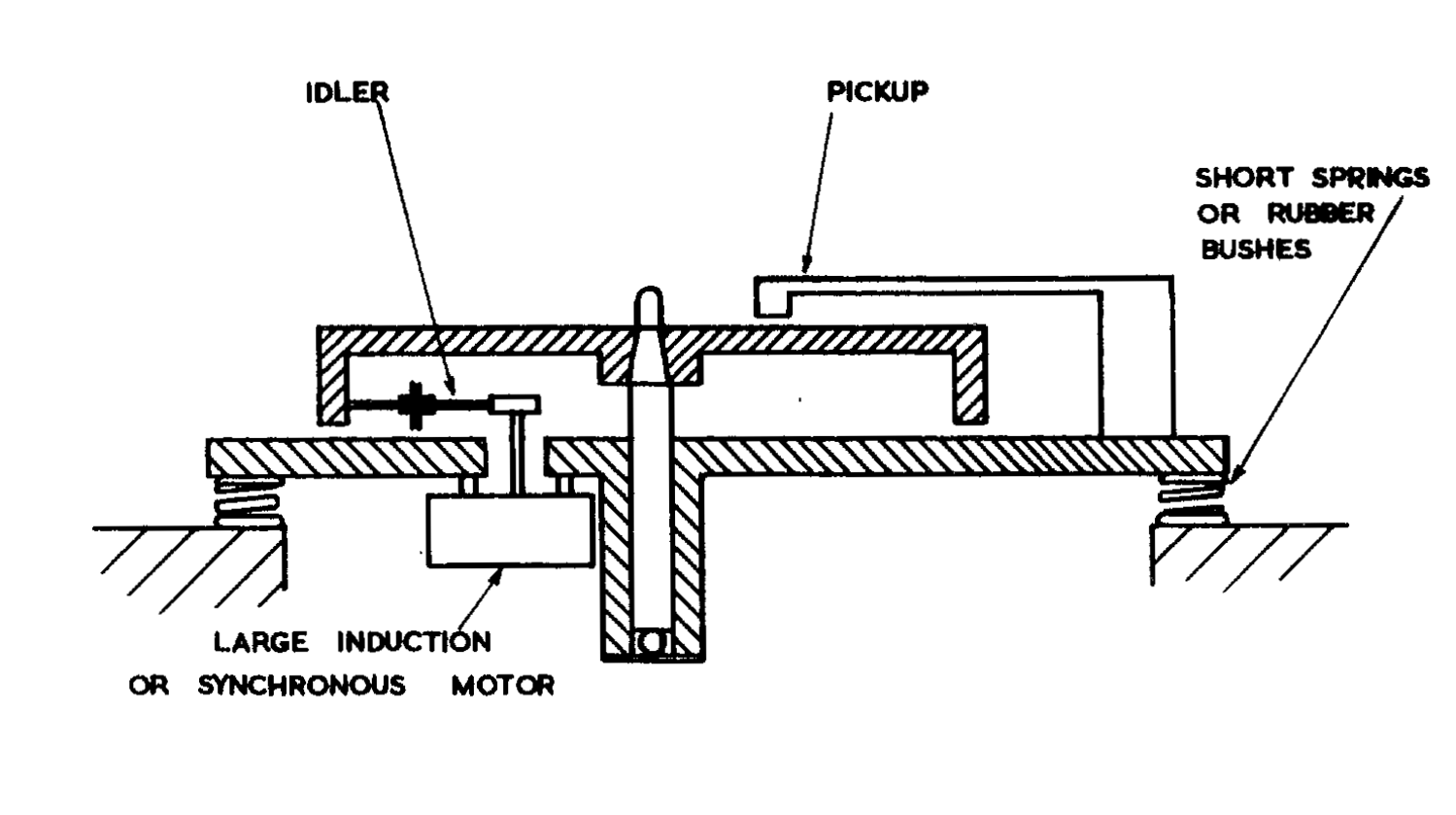
The earliest electric machines almost all employed a drive in which the motor spindle is coupled to the turning platter via a freely turning idler wheel fitted with a resilient rubber tyre. This type of drive permits significant power to be delivered to the platter, an important consideration in the days of heavy pickups and rough 78 RPM records. Idler drive machines maintained a place in record-player design almost through to the end of the heyday of records in applications in which the platter was required to spin up to speed very quickly, the most common being in broadcast radio.1
Once microgroove records and lightweight pickups became standard, the turntable drive was only required to overcome the relatively small friction forces of the platter bearing and lightweight stylus pressure. Thus, belt-drive turntables became fashionable; indeed being considered the sine qua non of record decks for many years.
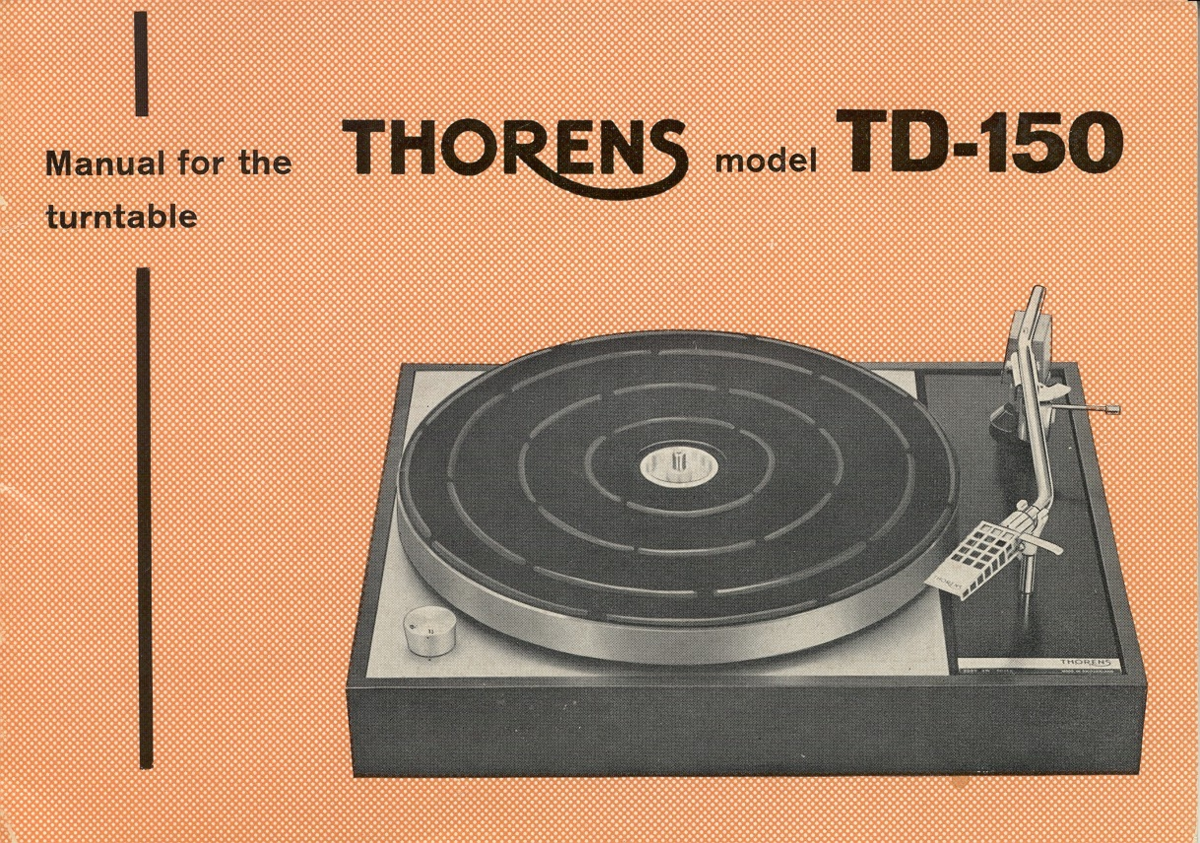
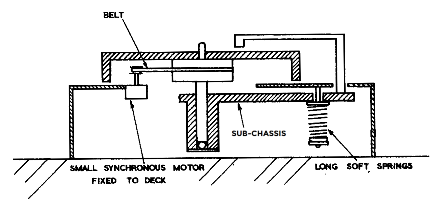
One of the earliest machines employing this technique was the Thorens 150 which employed a suspended sub-chassis on which were supported the platter (with its high-finish bearing) and the tonearm. This sub-chassis was isolated, via a compliant coupling, from the main chassis of the record player which supported the motor and controls. This arrangement, which originated with Villchur6 was widely copied by other manufacturers.
The highly compliant rubber-belt (used to transfer energy from the motor to the turntable platter) thus represents the only coupling between the two isolated parts of the record-player. The arrangement permitted a degree of isolation of inevitable noise and vibration of the motor itself from the turntable platter so that decks of this type set a new standard for a lack of low-frequency noise interference ("rumble").
The last type of drive is called direct-drive in which there is no indirect coupling between the motor and the platter. Instead, the platter is part of, or is fixed to, the motor spindle itself. Electric motors (especially the AC type) generally spin much faster than the rotational speeds required by records. For both idler drive and belt drive turntables this is no disadvantage as gearing the drive to the platter is accomplished via the differing diameters of the drive and the driven components. This is impossible with direct-drive and these machines, which represent the last types in the history of record players. These had to await the invention of brushless DC motors in which platter speed was not a function of the alternating current mains electricity.
A DC motor has a stationary set of magnets in the stator and a rotating armature with one or more windings of insulated wire wrapped around a soft iron core. In the simplest of motors, two magnets surround a single coil as shown below (the arrow marked B represents the magnetic field).
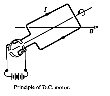
Any current-carrying conductor placed within an external magnetic field experiences a force, known as Lorentz force. In the simple motor illustrated, this Lorentz force forms a couple with the axis of the motor armature and thus creates a torque which turns the armature half a turn. Now, a motor which only turns half a turn isn't much good. But, if the direction of the electric current is reversed, the motor will make another half turn. So, what is required is an arrangement by which the current may be reversed every half turn so that the armature will continue to spin. If the armature includes two contact areas split via small gap (called a commutator) and the current is supplied to the coils via soft brushes which make contact with the commutator, the position of the commutator relative to the fixed armature and brushes will determine in which direction the current flows in the coil and a practical motor is created.
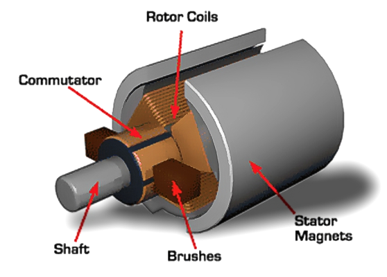 Real DC motors are rarely this simple but the principle always is. In practical motors, more magnets (poles) are arranged and often multiple coils in the armature too and this requires the commutator to consist of many contact areas (like the one shown right). Brushes are often made of graphite and are held against the commutator by springs.
DC motors have the great virtue that their rotational speed is proportional to the voltage drive. This is why DC motors of this type are used for everything from passenger trains to toys. To see why, we need to take a step back.
An early discovery concerning electricity and magnetism is that, just as a current carrying conductor in a magnetic field experiences a force which may make it move, a moving electrical conductor in a magnetic field creates an electrical current. So it is with electrical motors. If the source of the electrical power is removed and, instead, the armature is rotated by a source of mechanical power, then the machine becomes a generator of electricity.2
Less often realised is that a motor works as a generator even as it is working as a motor. The turning of the machine creates electricity which opposes the flow of electricity from the power source. This is known as a back electromotive force (or back EMF). The back EMF (expressed as a voltage) is always smaller than the driving voltage. If it wasn't we should have discovered perpetual motion! But it is very significant and does greatly reduce the power required to drive a motor once it is turning. Thus we can draw the circuit of a motor in this simplified form.
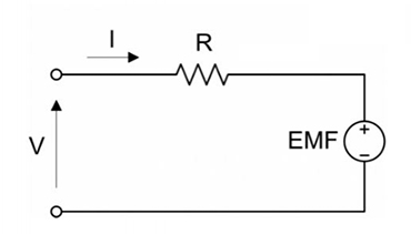
This circuit has three components, the winding resistances R, the applied voltage V and the back EMF generated by the moving armature.
Torque is directly proportional to the current flowing in the motor coil, because the force on a conductor in a magnetic field ∝ current passing in the wire (Lorentz force). Thus it's easy to see that, for a given, steady load, the driving current (I ) will remain constant, and that can only be achieved by the back EMF is directly proportional to the driving voltage V. Since the back EMF is directly proportional to the angular velocity of the motor (E ∝ ω), this ensures that,
V ∝ ω, where ω is angular frequency.
 As we have seen, in a DC motor a rotating magnetic field is produced by arranging the direction of the current to alternate in the coils of the armature with a commutator. With alternating current (AC) electricity, we have the great advantage that the current is switching direction 50 or 60 times a second all by itself, so no commutator is required in the motor.
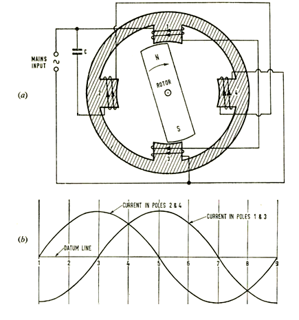
A simple example of an AC motor is illustrated right. The motor's stator (the unmoving part) has four poles, arranged symmetrically round the armature or rotor (the magnetised moving part).*
*Note the transformation between the DC and the AC motor: in the DC motor the coils are wound on the armature and the stator has the permanent magnets: in the AC motor, the coils are wound on the stator and the armature has permanent magnets.
Ignore the role of the capacitor and poles 2 and 4 to start with. Concentrate on poles 1 and 3, which are wound in series in such a way that, when the stator current is flowing in the direction that makes pole 1 a north pole, then pole 3 is a south pole. Clearly the rotor will rotate so that its unlike poles align with the stator poles.
As the AC current switches its direction, the situation is reversed. Just as with the DC motor, this change of circumstance causes the rotor to give another half turn. This pattern will go on and on and we have a motor of great simplicity.
Poles 2 and 4 in the diagram are similarly wound, but the current through their coils has a 90° phase difference between the current in the coils of pole-pieces 1 and 3 as a result of being supplied via a capacitor. This "staggering" of the alternating fields results in the production of a smoothly rotating magnetic field.
The rotor rotates synchronously with this rotating magnetic field and is thus a function of the AC supply frequency. Because of this, the speed of the motor is as accurate as the frequency of the mains (power-line) applied to the motor and - as this is very stable - these motors were eminently suitable to drive electric clocks and gramophone (phonograph) turntables.3 Nearly all record players during the heyday of records employed small synchronous motors.
The synchronous speed of a synchronous motor is given in (revolutions per minute) RPM, by:
RPM = 60 (f /P)
where (f is the frequency of the AC supply current in Hz and P is the pair number of poles per phase. Thus, a single-phase, 4-pole (2-pole-pair) synchronous motor, like the one illustrated above, operating at an AC supply frequency of 50 Hz and with two pole-pairs per phase, the synchronous speed is:
RPM = 60 × (50 / 2) = 1500
The only way this choice of turntable speeds may be accomplished with a motor which always turns at the same speed is via a primitive gearbox.
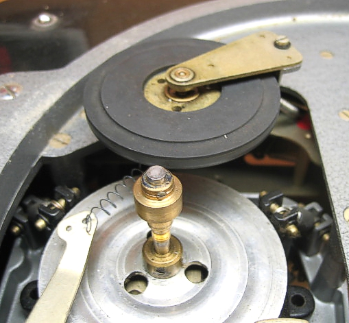
Idler drives often included a stepped pulley on the motor shaft to accomplish the gear-change by altering the vertical position of the intermediate rubber drive wheel so that it transferred the motor shaft drive to the hub of the platter at different ratios*. These mechanisms often appear rather whimsical (the one illustrated here is from the Garrard 301) but they were generally very reliable.
*A slightly peripheral point, but not unconnected, is that the diameter of the idler wheel plays no part in determining the speed of the platter in an idler drive. That is set entirely by the ratio of the hub and motor shaft diameters.
Thorens for many years used a type of dérailleur arrangement similar to a bicycle in which a belt guide, controlled by the speed selection control, slid the belt from a stepped pulley on the motor shaft to accomplish the appropriate gear change (limited to only two speeds). Not the apogee of Swiss/German engineering, this arrangement often gave trouble.
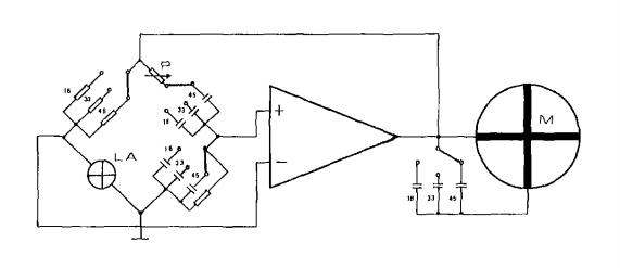 Perhaps, aware of this shortcoming, Thorens designed their top-of-the-line belt-drive deck, the TD-125, with electronic speed control. The concept being that, a synchronous motor will always turn at a speed determined by the frequency of the AC drive, so why not change the frequency of the drive to affect a gear-less speed-change?
Thorens approach was to drive the synchronous AC motor from a Wien Bridge oscillator arranged around an operational amplifier with enough power drive that it could drive the motor directly. The concept is illustrated right.4
Changing the turntable speed is accomplished by changing the frequency of the Wein-bridge oscillator by switching the value of the components in the feedback loop. A further capacitor is switched to provide the 90° phase shift for the auxiliary winding of the motor at the different drive frequencies. A potentiometer was introduced into the phase shift branch of the bridge which permits an additional small variation of the frequency to providing a pitch or fine speed control.
The motor-power upgrades offered by other manufacturers of decks driven by small, synchronous AC motors were based on this principle. Later designs used a high-frequency crystal oscillator and digital divider chains to derive the drive AC instead of using a Wein-bridge type oscillator.
The direct relationship between rotational speed and drive voltage in a DC motor is a very attractive property for a gramophone (phonograph) drive as multiple turntable speeds can be easily arranged without recourse to oscillators or gearboxes. But, DC motors have the disadvantage of the continuous making and breaking of the current path as the commutator rotates beneath the brushes which causes physical noise (the distinctive whirr of an electric motor) and electrical noise. These considerations ruled out the brushed DC motor as a power source for a gramophone (phonograph).
Developments in miniature, reliable electronics in the 1970s led to replacing the physical commutator with transistor switches. Not only did this produce a quieter motor with the no electrical interference, it guaranteed a longer lasting machine where the soft brushes never wear and need to be replaced. Of course, there is still the need to detect the position of the rotor relative to the stator, so that the appropriate current direction can be selected, this is accomplished by electronic sensors.
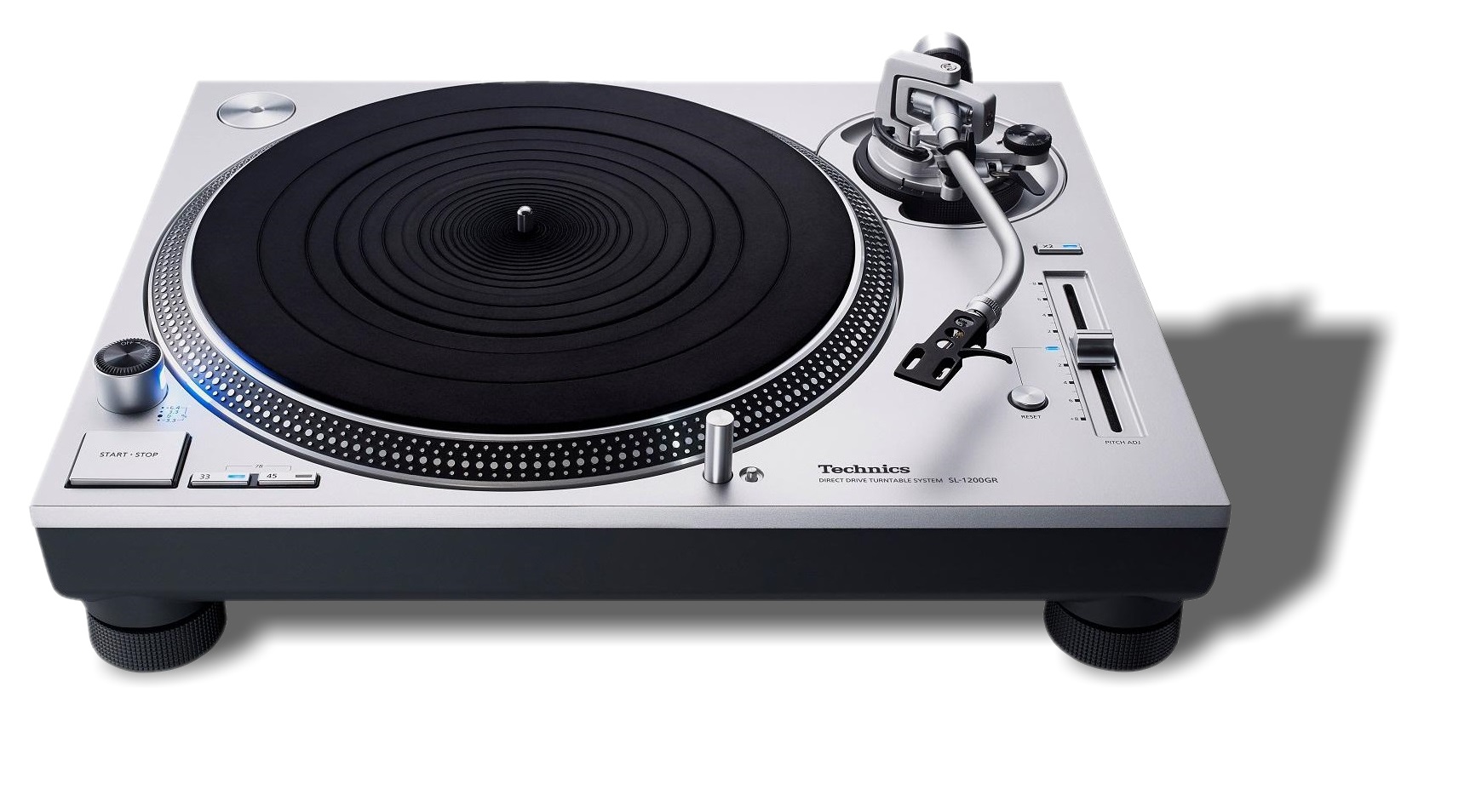
Brushless DC motors played a significant role in turntable design towards the end of the life of the record as a mass-market music medium; especially by Japanese turntable manufacturers. The iconic design here is the series of turntables known as Technics SL-1200 manufactured from October 1972 until 2010 (and again from 2016 to present) by Matsushita / Panasonic under the brand name of Technics.
The direct-drive DC motor fuelled the development of the turntable as a creative musical tool in the hands of club DJs who needed a high-torque motor for push-button cueing (like a radio DJ, a club DJ needs the deck to run up to speed very quickly) and wide-ranging speed control for beat-matching.
The superiority of the brushless DC motor to drive a turntable has resulted in the almost universal adoption of the type in contemporary turntable designs - even in Villchur-inspired designs.
The role of the modern turntable appears relatively straightforward. Its job is to,
The first requirement is clearly a function of the motor and drive mechanism, we'll look at how the best speed stability is accomplished. Central the rational assessment of different turntables are the effects known as wow, flutter and drift. A description of these effects and their measurement is given in Appendix A.
To what degree a pivoting tonearm accomplishes the ideal of following the groove is also considered below. There are a few surprises.
To the list above, we should also add that a very desirable virtue of a turntable is to provide
Some types are much better than others. But help is at hand.
The turntable platter plays a role in filtering the effects of this irregular torque. In the case of the belt and idler drive, the mass of the platter acts with the compliance of the belt (or rubber tyre) to filter the irregular impulsions of the motor. Increasing the mass of the turntable, or increasing the compliance of the tyre or belt, the better the suppression of the cogging, and the smoother the drive. We can say simply, the heavier the turntable, the better the flutter suppression to the point that increased mass of the platter will demand a more powerful motor which will generate more vibration.
 There is a downside to this; very little damping exists in this mechanical system. Some exists in the friction in the elasticity of the belt or tyre and the main bearing drag. But these are small and so, we are left with a relatively undamped resonant circuit which will "ring" at its natural frequency. This is a valid criticism of belt drive in which the compliance of the belt is significant.
This characteristic of a belt drive system also prohibits feedback speed-control because a resonant system in a closed-loop design would unquestioningly lead to oscillations.4
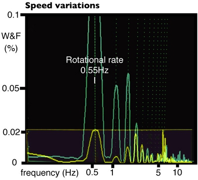
We are left with the fact that the speed of practical belt-drive turntables does indeed wander at the resonant frequency of the belt-platter dynamic system. It is a hallmark of the type and is easily recognised as in the spectrum plot of wow and flutter (example shown here, green trace). On good turntables this is reduced to well below the limit of audibility for wow and flutter.
In the direct drive, it is simply the platter's moment of inertia which filters out the effect of cogging torque from the motor and they do not benefit from the filtering effects provided by the resilient drive parts of other drive types. However in a direct drive deck, the transfer function relating drive voltage to speed does not contain frequency-dependent terms and is straightforward to implement. Therefore electronic filtering can replace the mechanical filters. By this means, speed stability is improved over the belt type by three to four times (yellow trace in spectrum plot of wow and flutter).
 In recent times turntables have been designed with, so called, acrylic platters. Some are genuinely made of acrylic (the synthetic polymer of methyl methacrylate known by the trade names Plexiglas and Perspex). Sometimes, the term should really be acetyl since it usually refers to polyoxymethylene (POM) which is an engineering thermoplastic used in precision parts requiring high stiffness, low friction, and excellent dimensional stability. Easily machined, coloured and finished, these polymer materials are acoustically "dead" compared with aluminium.
On the downside, the density of acrylic (1.19 × 10³ kg/m3) and acetals (1.42 × 10³ kg/m3) is a half to a third that of aluminium (2.7 × 10³ kg/m3), so platters made of these materials must be physically larger to give the same degree of flutter supression as an aluminium platter.
Moreover, these polymer materials are not electrically conductive and would seem to eschew knowledge gained concerning a conductive platter and the vital role it plays in reducing static electricity build-up on the playing surface of the record. The same criticism could be levelled at acetyl or acrylic turntable mats, or indeed those made of glass, cork etc.
 The main bearing for the platter must be on a very high finish if it is not to cause noise and vibration called rumble. Fortunately, the bearing is not called upon to carry a heavy load and only turns very slowly.
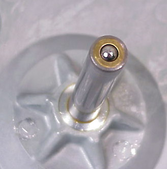
A common arrangement is for a highly finished steel shaft to run in a sintered-bronze7 sleeve, the weight being supported by a single ball running in the slightly cupped shaft and bearing on a hardened-steel thrust-plate. Many years ago, Thorens demonstrated that a bearing of this type was capable of generating rumble some 10dB below that recorded on the record due to the lathe.5
However this has not stopped almost endless innovation. Teflon filled with molybdenum disulphide lubricant has been substituted for the sintered-bronze lubricated sleeve, POM has been employed for the thrust-plate and the bearing is sometimes jewelled by substituting the metal ball bearing for one made of ruby.
Fluid bearings have been employed and the German company Clearaudio manufactures a magnetic bearing in which the two moving parts are formed of two pole-opposed ceramic magnets. A ceramic axle rotates in a sintered-bronze sleeve to keep the bearing centred but it carries no weight. That role is played by magnetic levitation. In common with other exotic bearings the lack of metal-to-metal contact prevents the platter from being earthed via the bearing which is necessary if the platter is metal.
II. Follow the groove
The tonearm, which provides the mounting for the all-important cartridge, is a freely pivoted arm which swings across the disc radius during play. Arranged to swing comfortably beyond the full radius of the record, the tonearm may be parked safely whist discs are loaded and un-loaded.
Tonearms are designed to possess a degree of vertical rotational freedom too, to allow the cartridge to be lowered onto the record for playing and lifted, when finished and to cope with record warps. The two points of rotation (lateral and vertical) must be coincident and a two-axis gimbal is a very common arrangement. The quality of the gimbal bearings is very important: they must offer minimum bearing friction, and they should have no play. A common (and excellent) bearing arrangement is an adjustable tapered pivot sitting with its apex in a miniature ball-race.
The weight of the phono cartridge is always more than the desired tracking weight, so the tonearm incorporates a counterweight behind the pivot point, partially to balance the cartridge weight and reduce the tracking force to somewhere in the region of 2g (this being considered the limit beyond which record damage occurs). Often the counterweight is arranged and calibrated so that the balance may be set to give the correct tracking weight.
 In the recording process, the cutter chisel is moved on a parallel bar across the disc radius. Ideally, a reproducer would track along a radius in order to maintain the stylus at right-angles to the groove. In a normal record deck, the stylus and pickup are mounted at the end of a long tone-arm which pivots around a point. The pickup thereby traces an arc - rather than a radius - across the record surface.
This drawback is still discussed ad nauseam, yet a complete mathematical analysis and - almost totally - acceptable cure have been known for nearly a century. All modern tone arms are arranged to overhang the centre of the record, and have a "crank" so that the cartridge sits at an angle relative to the tone arm. By these two simple geometrical means, the tracking error (the angle of the cartridge relative to the tangent of the groove) is reduced to a few degrees at any point on the record. Discussed in greater detail on this page. Stereo Lab has a mechanism for improving on the various distortion mechanisms which are due to mechanical limitations in tracing a groove with practical stylus shapes.
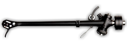 The tonearm offset angle was, at one time, universally achieved via a bend in the arm tube, but this places the arm centre of gravity outside of the axis of the arm. To alleviate this, manufacturers employed a second-bend and created the S-shaped arm. Some modern tonearms tend to incorporate the offset angle via a crank in the cartridge platform. The simplest straight tonearm is a cylindrical tube. But tubes have a marked resonance (think tubular bells). To counteract this, the straight arm may be flared as illustrated right.
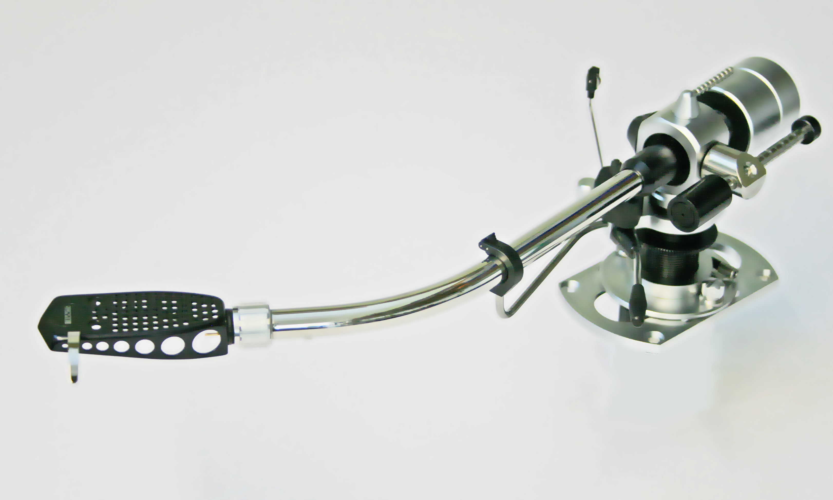
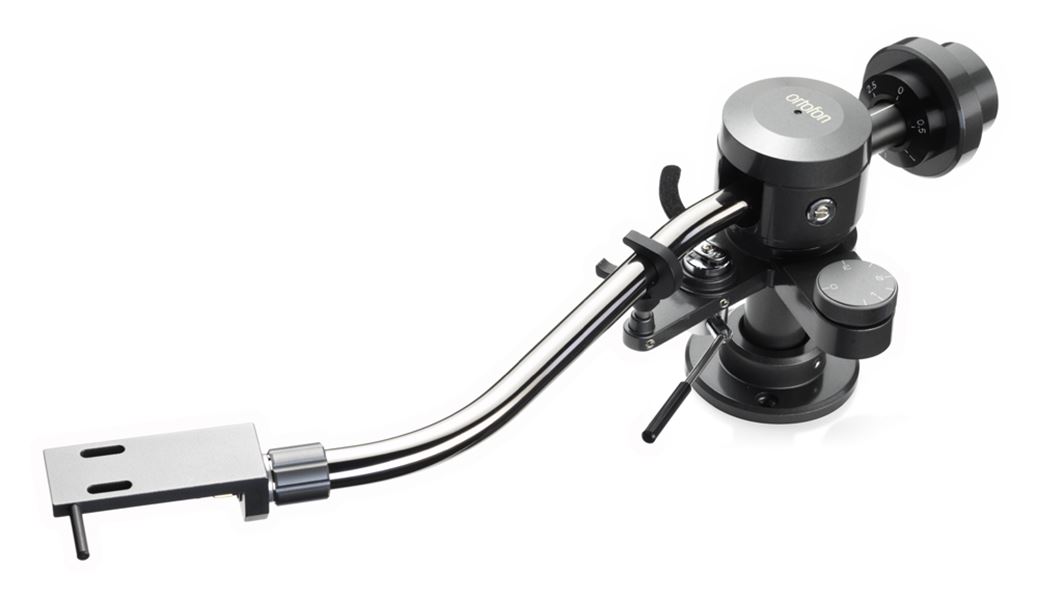
The bent arm design (single crank or S-bend) is still widely used as the straight section directly behind the cartridge mounting permits a screw-locked connector to be incorporated so that a cartridge mounting section (the headshell) may be removed. This connector is a real boon to the record collector and archivist because it means different cartridges with (for example) different styli may be fitted to different headshells and be swapped quickly and safely.
Interaction of cartridge-compliance and arm inertial-mass
It's a common observation that, when a stylus is lowered onto a record, it "sinks" slightly as the stylus suspension is compressed, This is due to the stylus compliance which is a measure of the 'springiness' of the suspension and denotes the distance relative to the unloaded position the stylus will sink as a result of a force acting on it. This compliance is a vital component in the reproduction system because it is what decouples the stylus relative to the cartridge and tonearm. It separates the performance of the dynamic system at sub-audible and audible frequencies.
Remember, it is the movement of a stylus relative to the cartridge which produces the electrical signals. Thus, for audible signals, we want the cartridge on its tonearm, to "hover" at a constant height and position. But, as the stylus moves laterally very slowly (or up and down due to warps), we want the cartridge to follow these movements and thus produce negligible signal.
The watershed between these two regimes is known as the transition frequency or more commonly as the arm resonance Fr which is calculated,
Fr = 1 / [2.π (M.C) -½]
Where M is the effective mass of the of the entire tonearm and its heavy counterweight as seen at the stylus tip (in grams) and C is the compliance of the stylus suspension (in cm/dyne). Fr is in Hertz.
NOTE. The c.g.s. units were retained in this section because in so much of the literature concerning phono cartridges and tonearms, these rather outdated units are used. This reflects the period of course, but it may also be because SI units of metres and Newtons do seem huge when thinking about precision engineering at this scale. For correctness, the dyne = 10 × 10-6N (10μN).
We want the lateral arm resonant frequency to be greater than 1Hz so that the effect of the stylus moving towards and away from the turntable centre as a result of eccentric centre holes is negligible. And we require the vertical arm resonant frequency to be greater than about 7Hz so that signals are not obtained from ripples and warps. Yet, both resonance frequencies should be less than about 20Hz to permit a flat frequency response down to the lowest musical notes. This doesn't gives us a lot of "wiggle-room", so the matching of the arm moment-of-inertia to the cartridge (its mass and compliance of its suspension) need to be done with care.
One of the complications to the cartridge designer is that the vertical compliance of the stylus support is statically preloaded by the vertical tracking force, whereas the lateral compliance is not. In practical designs, the downforce is balanced by a suspension rod — often a short length of piano-wire connected to the pivot point of the stylus assembly. This suspension rod bestows strength to the vertical support. Without it, the stylus would collapse under the downforce when playing for any length of time. Clearly, there is no similar requirement for the lateral support which supports no static force.
Yet the dynamical requirements imposed by the recorded material are symmetrical. The stylus must track either lateral, vertical, 45° right, or 45° left modulation with equal facility and that demands that the compliance of the stylus suspension should be the same for lateral or vertical motion. Obtaining similar compliance under such different circumstances is part of the art of cartridge design and is often not entirely achieved, so that lateral compliance is greater than vertical compliance in practical designs. As far as considering the interaction of arm and cartridge is concerned, if we concern ourselves with the vertical case (where the suspension is sometimes somewhat stiffer), the lateral case "comes out in the wash".
Taking an average figure of vertical compliance as 15 × 10-6 cm/dyne and choosing an optimum vertical resonant frequency of 10Hz. We can calculate the required moment of inertia to satisfy these conditions is just 17g.
Given that the cartridge weighs about 8g, we can see that, for the designer, a low effective mass tonearm must be conceived for which the mass of the various construction elements is reduced to a minimum. Magnesium is often employed because it has two-thirds the density of aluminium. The old engineering maxim, "simplificate and add more lightness" is as appropriate as it was to the aeroplane designer8.
The concern is that a massive design might better absorb the energy imparted to the cartridge from the modulated groove (only a tiny fraction of which is converted into electrical energy). Once lightweight materials are prioritised, the pickup cartridge cannot be considered a rest mass above the tonearm resonant frequency, even if the cartridge possesses high compliance. Consequently, the tonearm itself must be designed considering its vibrational properties. This is the challenge in tonearm design and has driven a modern (and possibly misguided) tendency towards cartridges of lower compliance combined with more massive arms. 9
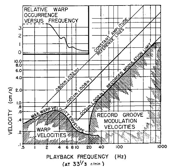
A study of the vertical frequencies derived from warped LP (33⅓) records was made by a team at Shure Brothers Inc. back in the 1970s10. Their results are summarised in the graph which illustrates that most warp frequencies lie below about 7Hz. Whilst the designer aims to set the arm vertical resonance frequency in the dead-zone between warp excitation and wanted groove modulation, that does not mean they the resonance is not continually excited.
Even on a record which is perfectly plane, external excitation (foot-falls for example) and even groove modulation itself which results in uneven drag on the stylus, provokes this resonance. Needle-drop waveforms looked at with a DAW often betray almost continual oscillation to a greater or lesser extent at the transition frequency. This is pernicious.
The large, very low frequency signals are unwanted, but they may - at least - be filtered. Stereo Lab incorporates filters to remove this low frequency "clutter". Linear-phase types, their performance exceeds anything possible in an analogue preamplifier. But the low-frequency vertical "bouncing" of the cartridge causes frequency modulation of the programme signal as the cantilevered stylus scrubs forwards and backwards. This is not insignificant.11
For example, at vertical arm-resonance, total amplitudes of 0.8mm are easily observed by eye. If the resonance frequency is 8 Hz, the resonance velocity will be about 2 cm/sec. This velocity will produce a "scrubbing" velocity of 0.6cm/sec along the groove axis. The groove speed at a 4.5 inch radius is about 40 cm/sec; so the frequency modulation will be about 0.6/40 or 1.5 per cent and easily audible as this clip shows. The first part is a standard 3150Hz tone, the second is modulated to model the effect of the scrubbing motion described above.
Another less obvious but highly detrimental consequence of the vertivcal arm-resonance is that the stylus force is "used up" when the arm is vibrating. In the previous example, if the compliance of the pickup is assumed to be 20 × 10-6cm/dyne, 2.0 grams of stylus force will be required to accommodate the arm vibration alone. This is as large as the usual stylus force, so mistracking is quite certain at the extremes of the vibration. That sounds like this:
Considering the entirely audible problems caused by undamped oscillation at the arm vertical resonant frequency, it seems odd and sad that so little effort appears to have been spent in inventing cures for it.
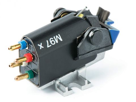
In 1978, Shure built a simple and elegant damper into the V15 Type IV cartridge 11. This Dynamic Stabilizer was retained as a feature on the modern M97XE cartridges until Shure ceased phono cartridge production in 2018.
Shure's contribution was welcome and worked well. But adding anything to the tonearm will always increase the moment of inertia - especially when added at the furthest point from the pivot. So damping is much better added as close to the pivot-point as possible.
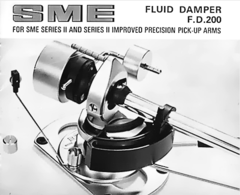
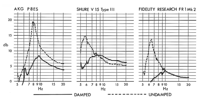
Many years ago, SME offered a damping kit for their Series II tonearms, and Kab Electro Acoustics of New Jersey make a fluid damper for the standard Technics tonearm which closely resembles the original SME kit. Both kits consist of a small paddle which is clipped to the tonearm tube near the pivot and travels in a tray of thick silicone oil which fits around the tonearm base. Impressive results using the SME kit with three contemporaneous cartridges are illustrated in the adjacent frequency-response graphs.
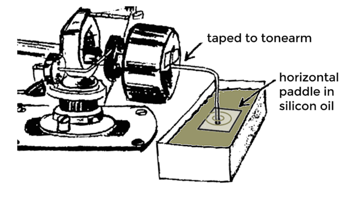
 A DIY damper of such extreme simplicity that anyone can experiment with tonearm damping was described in the Journal of the Boston Audio Society11. A piece of thin brass rod is taped to the the back of the tonearm, and "paddles" fastened to the on the end of this rod. The paddles are submerged in STP oil additive held in a small metal trough.
The author reports that prior to the modification, warped records, caused the arm to bounce several times after each sharp warp such that the the audio was modulated by this movement (in the manner described above). He notes that the effect was particularly evident with organ recordings. Following the modification with the paddles, the previously annoying records were playable with absolutely no "bounce," or warbling tones. He reported, "The stylus stays virtually motionless (to the eye) relative to the tonearm, so I'm not generating low-frequency tones to modulate all my music.
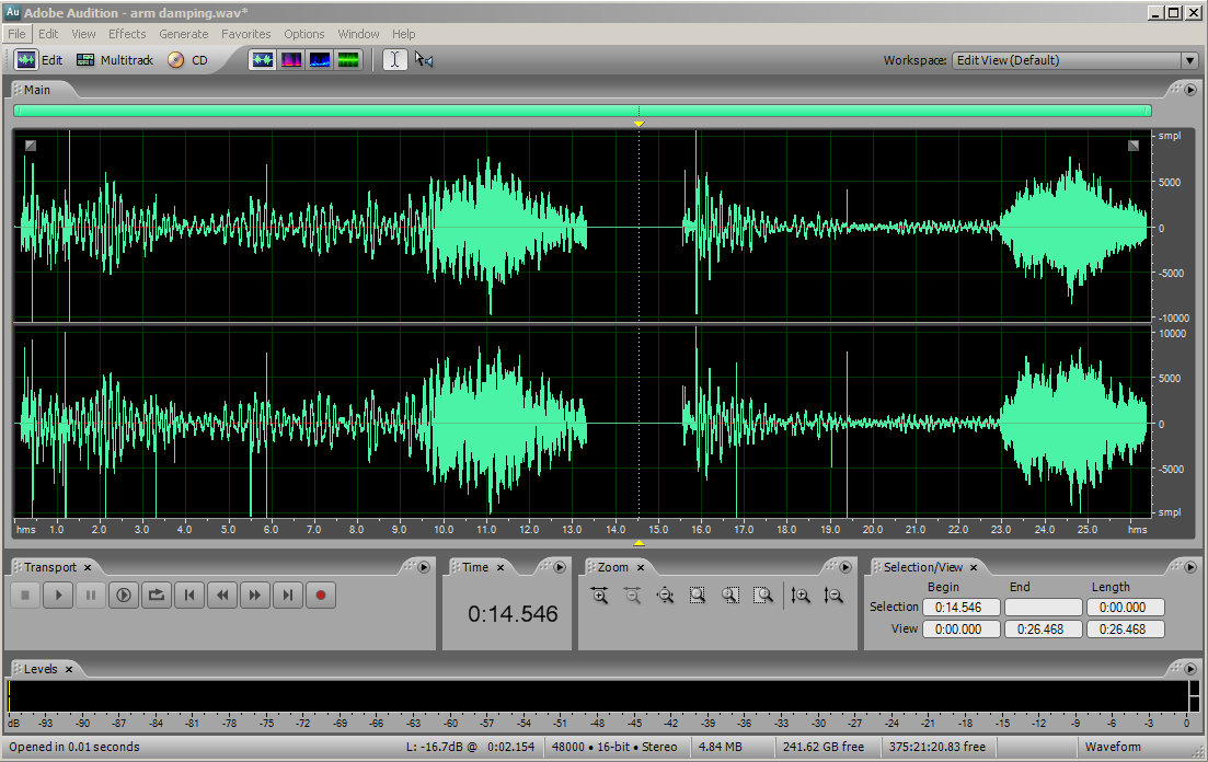
The illustration shows our version which omitted the vertical paddle and using a low viscosity silicon oil instead of STP oil additive. The screen-grab illustrates the effect on vertical resonance (in this case deliberately provoked by a rather poor match of tonearm and cartridge). An identical section of the lead-in of an LP is illustrated twice: the first without the damper; the second with. As its inventor Mr. Graham advocates, Try it — you'll like it!
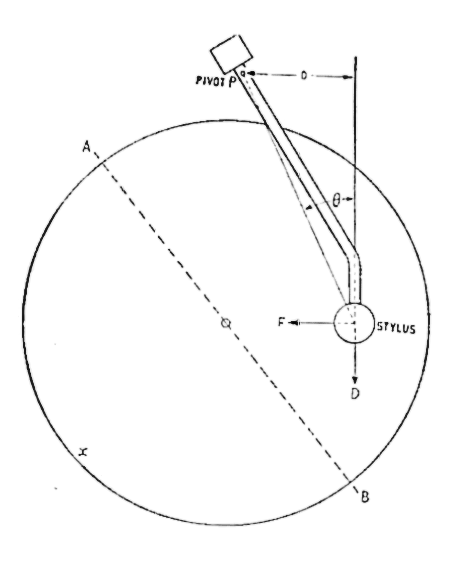
A typical cranked arm is illustrated. As the groove passes the stylus it provides a forward drag which is tangential the record groove at the point of contact. This is in the direction D on the diagram, and its line of action is displaced from the pivot (P) to the extent of the linear offset (0). Thus, this forward force produces a clockwise moment about the pivot which tends to press the stylus against the inner groove wall in the direction F.
In various circumstances, this can lead to channel imbalance. CD-4 quadraphonic records offer a very real demonstration of this effect if not properly balanced by an opposing balancing outward force arranged by the tonearm designer.13
This force is sometimes arranged by means of a small extra weight (as seen on the SME Series 2 arm photograph above), or it is arranged via a small coil spring or a magnetic assembly.
The three types of record-deck, defined by drive type, are illustrated below . From a suspension point of view, the direct drive and the idler drive are identical. The only alternative is the Villchur (suspended sub-chassis) arrangement. A modern artifice used in many record players of striking visual design is to set the motor (usually a brushless DC type) in an entirely separate housing and drive the turntable platter via a belt, or belts, which run on its outer rim. The platter and tonearm share a common, decoupled chassis. A moment's thought will reveal that this is simply elegant variation on the Villchur design.
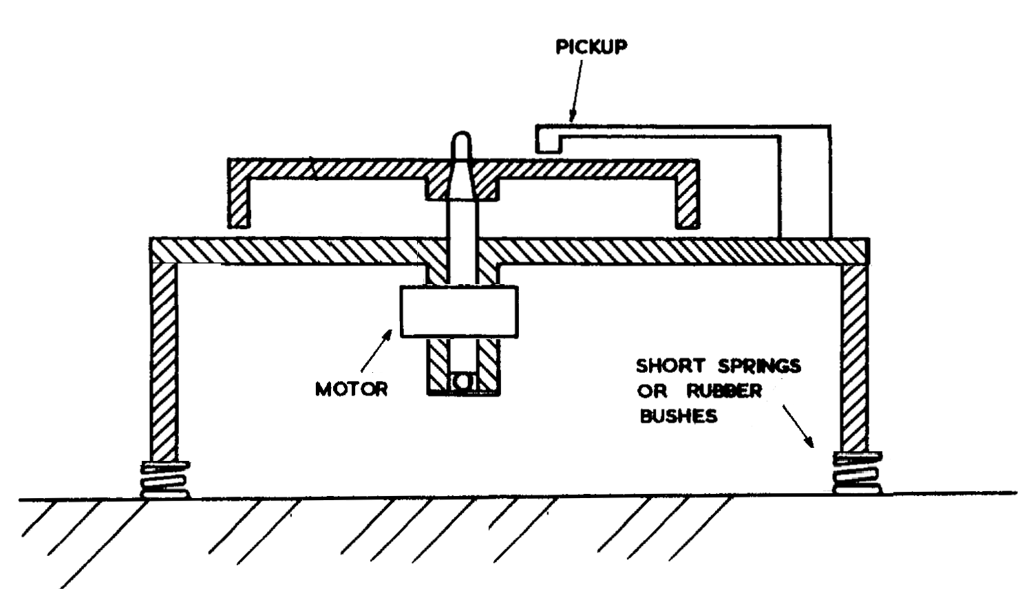
Turntable suspension types: idler and direct are effectively identical (right-click to see larger illustrations)
It's worth asking the question, what are we trying to isolate? The answer is to prevent external vibration (whether derived from the amplified audio, or from vibration due to footsteps and physical shocks) from exciting the vertical tonearm resonance. For, if this is excited enough, to all the effects described above may be augmented the stylus disengaging from the groove altogether (we say, the stylus "jumps").
We are thus principally interested in the attenuation the turntable suspension offers at the vertical tonearm resonance frequency. This is especially significant as the resonance of suspended wooden floors is often in the region of 10Hz and thus they do a great job of communicating excitation in the frequency region which coincides with arm-resonance frequency.
Mathematically, the attenuation offered by the suspension reduces to the equation,
Tf = [1 - (fx / fy)2 ] -1
Which defines Tf, the transmission of the applied vibration (fx), in relation to the resonance frequency of the turntable (or sub-chassis) on its springs (fy). This is the transfer function of a low-pass filter and is plotted below.
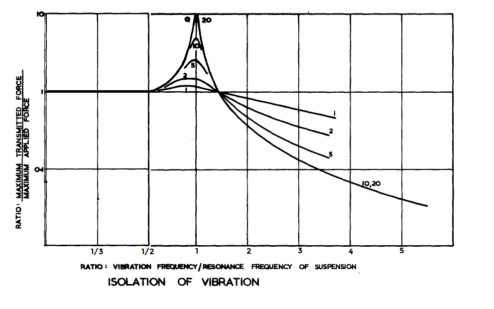
What all the curves reveal is that the resonance frequency of the turntable suspension must be significantly below the vertical arm-resonance frequency for it to offer any significant degree of isolation.
We have seen that the transition frequency for the cartridge compliance and tonearm effective mass is set for us by other considerations at about 10Hz with very little scope for alteration. So, for the turntable suspension to be more than useless, it must have a resonant frequency of 5Hz and preferably, significantly below.
This is a very low frequency: the classic Villchur-type turntable comes in at the top of this range (usually about 5Hz). Attempts made to better this necessarily involve the use of a very heavy sub-chassis. This has been the approach of several manufacturers of very "high-end" turntables (see below). Significant benefits have been reported when the suspension resonant frequency of a Villchur type turntable can be reduced to around 1Hz.15
If the suspension has a resonant frequency above the vertical tonearm resonance, it offers little or no attenuation at all. We can see why the resilient feet fitted to most direct drive decks are ineffective.16
The curves illustrate that a poor selection of suspension to arm-resonance ratio can have a lamentable effect. If the frequencies nearly coincide, the results may be many times worse than if no suspension existed at all. Given how close these two frequencies often lie in the Villchur design, it is probably unfortunate examples of poor matching of this type that has given rise to the myth that the direct-drive decks have superior suspension. They don't, but, at least. they don't make things worse.
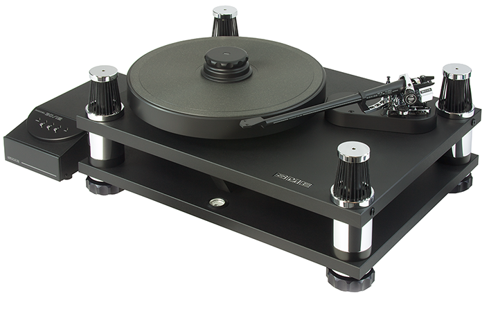
The SME Model 30/12 turntable is an example of how the Villchur turntable-concept may be developed to lower the resonant frequency of the independant sub-chassis. The devil in the detail is that the resonant angular frequency (ωo) of any simple harmonic oscillator made of mass M (kg) and compliance C (metres/Newton) is given by
ωo = √(1/CM)
So, doubling the mass with a view to reducing ωo, will only result in 1/√2 reduction in frequency.
There is thus a law of diminishing returns and a great deal of extra mass needs to be added substantially to reduce the resonance frequency.
In the SME design, the massive 30kg top-deck, which carries the platter and tonearm, is suspended from pillars in the baseplate via elastomer suspension cradles. As expected, the motor is mounted on the baseplate with the drive pulley protruding through a hole in the top-deck so that the belt can pass around this and the turntable hub. Motor control is via the separate control unit.
Looking again at the graph above, the effect of damping on the suspension system is interesting. Low damping (higher Q), although it results in a faster descent into the stop band, results in a much greater susceptibility to vibration at the turnover frequency itself. The SME design incorporates four fluid dampers, one in each of the supporting columns to control the Q of the suspended top deck.
The use of elastomer supports makes the SME design feasible. If springs were used to support 30kg, they would be impractically long. Unlike metal springs, the compliance of elastomers is non-linear and, if used over the right portion of the load-deflection characteristic, the desired compliance may be obtained with much smaller deflection.
Happily, readily available elastomers may be employed to create a simple, isolation platform with a very low resonance frequency on which a more modest record-deck may be placed.
The design of this vibration isolation platform is due to TJ Hertz, the English DJ and producer known as Objekt17. Developed to prevent structure-bourne feedback by isolating Technics SL1200 series turntables during a DJ performance, the design has applications for anyone wanting to isolate a turntable from external vibration.
An elastomer device which fulfils the requirement of high compliance at small defelection is a rubber sphere, which initially at low loads is extremely soft and hardens up rapidly with increasing loads to become very stiff. Care must be taken however, that the working portion is reasonably linear, to avoid motion at harmonic frequencies. In other words, we need to chose our balls carefully!
 Hertz initially used squash balls in the design (apparently this is a common DJ trick). Later, he discovered that the balls used in frontenis (a sport somewhere between tennis and squash played in Mexico, Spain and Argentina) could be cut in half to give the same suspension performance as squash balls but with the great advatage that, being halved, they don't roll.
Hertz uses a concrete paving slab (at least 50mm thick) under each deck supported on two halved frontenis balls; one under each corner of the slab.
The density of concrete is about 2.3 × 10³ kg/m3, so a slab 500mm × 500mm × 50mm weighs 29kg and the downforce on the balls is about 290 Newtons.
The combined suspension "settles" by about 18mm when this load is applied implying that the compliance of the four balls in parallel is 62.5 × 10⁻⁶m/Newton. (This checks with independent data that the compliance of a complete squash ball is approximately 0.25 × 10⁻³m/Newton and still on the linear part of its force/deflection curve at that degree of compression.)18
Combining these in the equation,
ωo = √(1/CM)
we calculate, ωo = 23. Dividing by 2.π = 3.7Hz
We use a variation on Hertz' design in the Pspatial Audio office, using marble which is only slighlty denser than concrete but much prettier. It works very well at isolating floor-borne vibration when we use one of our direct-drive decks for needle-drops.
Drift, wow and flutter are all caused by undesired frequency modulation of the signal by an irregular motion of the recording medium during analogue recording, duplicating, and reproducing processes. All three effects are therefore really categories of effect due to the same underlying cause. The effects are divided because of the different subjective effects of this type of distortion according to the frequency of the modulation.
An audio file is available here in which a 3150Hz tone (the frequency normally used for measurement of drift, wow and flutter) is frequency modulated in a sweep from 0.1Hz to 100Hz (deviation 100Hz). The three different effects described above are recognisable.
Measuring instruments use a frequency discriminator to translate the pitch variations of a recorded tone into a wow and flutter signal which may be filtered (weighted) and analysed in various different ways depending on the requirement. The weighting filters exist to sensitise the measurement in the modulation frequency range which causes the greatest subjective impairment (4 to 5Hz). The filters introduce attenuation above and below this frequency.
Various standards specify the exact weighting filter and rectification necessary if the signal is to be displayed on a meter, as well as the methodology which should be employed in recording a single figure from a changing signal.19
Turntable speed accuracy is measured using a test disc cut with a 3150Hz steady tone. DIN 45 465 is one such and has the great attribute of a locked outside groove which allows the disc to be carefully and accurately centred, thereby taking disc eccentricity out of the equation. With this done, it is possible to measure down to around 0.06% unweighted wow, sufficient to identify the performance of top quality turntables. The best direct-drives manage this level of performance. Most belt drives are worse with measured wow being about 0.12% pk = 0.24% pk-pk.
For the design engineer, a frequency transform of the demodulated wow and flutter gives more information than a single-figure ever can; revealing periodic eccentricities which may be "tracked down" and rectified.
The audibility of wow and flutter is discussed on this page.
1. Radio DJs cued records by placing the tonearm on the record and manually spinning the record back to find the exact point at which they wanted the disc to play from (back-cueing). The tonearm was left in this position until the track was required and the motor started via an electric switch.
2. One might almost say that the entire modern world depends on this discovery.
3. How accurate is mains (power-line) frequency?
 Over comparatively long time scales, of the order of a day or so, the accuracy of the average mains (power-line) electricity frequency is excellent; hence the accuracy of electric clocks. This is due to the power companies locking the average mains frequency to UTC atomic clock time. European power companies control the frequency of their grid every day so as to make the total number of cycles in 24 hours equal exactly 50 x 60 x 60 x 24 = 4,320,000.
At small time scales, of the order of a second, the frequency stability of the mains (power-line) is very good too. This is due to the mechanical inertia of the generators in the power station. In effect, the record turntable is locked to a 50 ton flywheel formed by the rotor of the turbine and generator.
Over the period of minutes, the frequency of the mains can vary. When demand momentarily exceeds generation, the missing energy is supplied by the kinetic energy of the generators’ rotors and the synchronous machines slow down. By the same token, if capacity exceeds the load, the frequency increases. These variations are strictly limited because an interconnected electricity grid could not function if these frequency fluctuations were not very small.
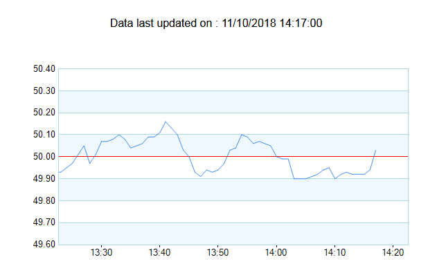
For example, in the UK, National Grid has a licence obligation to control frequency within ±1% of nominal system frequency (50.00Hz) and they do this by ensuring that sufficient generation is held in readiness to manage all credible circumstances which might result in frequency variations. In normal circumstances, regulation is substantially better than this ±1% figure. The graph shows an example of the recorded UK grid frequency variation over an hour. The ±0.1Hz (±0.2%) performance is typical of the UK grid. This degree of stability is adequate to justify the use of AC synchronous motors for turntable drives. Indeed, most disc-cutting lathes use synchronous motors when the record is cut anyway.
In North America, the situation is a little different and more complicated, and data is harder to come by. The error in a synchronous clock has to exceed a certain threshold before frequency correction is applied. The thresholds differ according to the part of the country and range from 2 to 10 seconds. When the threshold is exceeded, a correction of ±0.02 Hz (0.033%) is applied either on the hour or on the half-hour.
In areas of the country where there is wide interconnection, with many generators and loads, precise frequency control is important. As it is in the European grid. However, smaller power systems, not extensively interconnected , will not maintain frequency with the same degree of accuracy and system operators may allow system frequency to rise during periods of light load, to maintain a daily average frequency of acceptable accuracy.
Data is hard to come by, but taking the worst-case possible in the time between a correction "window", which would involve losing or gaining 10 seconds (600 cycles) in 30 minutes (60 × 60 × 30 = 108,000 cycles). Even this degree of frequency variation is only just over ½ per cent. Not really enough to throw suspicion of utility power-line frequency variation on the quality of reproduction (or recording because most lathes use AC power-line synchronous motors).
4. An electronic forward drive in transcription turntables. Hirsch F.H. (Thorens-Franz AG Wettingen, Switzerland) Presented at the 37th JAES Convention October 13-16, 1969
5. Op. cit.
6. A New Turntable-Arm Design. Villchur, E. Audio Sept & Oct 1962.
7. Sintering is a process in which a metal part is formed under pressure and heat from a metal powder without melting it to the point of liquefaction. Sintered-bronze is often used in bearings because it is porous and allows lubricants to flow through it or remain captured within it.
8. The axiom is attributed to William Bushnell Stout, designer of the old Ford Tri-Motor aeroplane.
9. In considering the various components of the tonearm, we should bear in mind that the inertial mass of a pivoted straight bar is set by,
θ = m × d 2
where θ is the moment of inertia in gram metres2 of a point mass m in grams that is located a distance d millimetres from the rotational centre of the system. Because d is squared, it should alert us to the important fact that distance (from the pivot) dominates over straightforward mass. This is why, for example, a counterweight of high density material near the gimbal is greatly preferred to one of lower density further away.
10. Record Warps and System Playback Performance. Happ and Karlov, presented September 1973, at the 46th AES Convention.
11. Phonograph Reproduction - 1978. Anderson, Happ et al. AUDIO May 1978
12. Tonearm Damping. Graham, R. The BAS Speaker (Journal of the Boston Audio Society) Volume 3 No. 4, January 1995
13. Dynamic Side Thrust in Pickups CRABBE, H. J. F. WIRELESS WORLD, MAY 1960
14.The Performance of Pickups at Low Frequencies and Isolation from External Shock. Barlow, D. A. 50th AES Convention March 1975
15. The Development of a High Quality Turntable. Barlow, D.A. 47th AES Convention March 1974
16. We have measured the standard feet supplied by Technics to resonate with the deck weight around 30Hz. In the office where we test Stereo Lab, we have both a belt drive type (Thorens 150) and a direct drive deck (Technics SL-1200 Mk. II). The office has a suspended wooden floor and there is simply no competition: the Thorens offers much greater isolation against vibration that the Technics.
17. TJ Hertz (a.k.a. Objekt) is considered one of techno's most dynamic DJs. The isolation platform of his design is specified as part of the technical rider to his artist contract.
18. The dynamic behavior of squash balls. Lewis, G.J et al. The American Journal of Physics. March 2011. This graph (of yellow dot squash-ball behaviour) is from that publication.
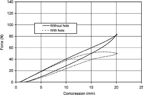
NOTE: Elastomers, or vulcanised rubbers (in which sulphur has been added to natural rubber) contain long chains of randomly oriented molecules of mainly carbon, hydrogen and oxygen. These long chains are subject to entanglement and cross-linking due, in the case of vulcanised rubber, to the added sulpher. As stress is applied to the elastomer, internal rearrangements of the polymer chains occur. When the stress is released, the crosslinks cause the chains to spring back to their original shape..... at least, nearly.
Elastomers are not perfectly elastic and lose energy during the compression (or tension) and subsequent recovery. Unlike purely elastic substances, elastomers are viscoelastic which means that a substance has an elastic component and a viscous component.
Purely elastic materials do not dissipate energy (heat) when a load is applied and then removed. Whereas a viscoelastic substance loses energy when a load is applied, then removed. Hysteresis is observed in the stress–strain curve, with the area of the loop being equal to the energy lost during the loading cycle as illustrated in the graph. A viscoelastic element may be modelled as a perfect spring with a damper. An elastomeric squash ball (or halved frontenis ball) used in a suspension as in the vibration isolator, is thereby naturally damped.
19. AES6-2008 (r2012) - Method for Measurement of Weighted Peak Flutter of Analogue Sound Recording and Reproducing Equipment. Published by Audio Engineering Society, Inc.
Pspatial Audio Home page
For all support issues, go here.
For Pspatial Audio sales, email: sales@pspatialaudio.com