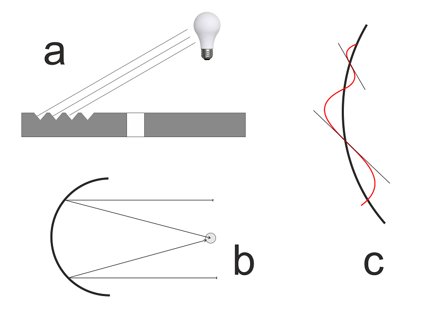
It has been recognised since the earliest days of disc recording, that if a phonograph record is illuminated with a grazing light so that the beams of incoming light are arranged to reflect off one wall of the v-shaped groove (illustration a), interesting patterns of reflection are observed.
In the nineteen-thirties, two German engineers (Buchmann and Meyer)¹ realised that these reflections were more than simply interesting. Provided certain conditions applied, they showed that the reflected patterns gave a direct measure of the information recorded in the grooves of the record. The understanding of this phenomenon greatly aided in the development of recording quality from records.
Buchmann Meyer Overdrive
Buchmann and Meyer realised the when a record is illuminated as illustrated (b), the gentle curve of the groove acts upon the incoming parallel beams of light as a curved mirror, concentrating the beams together at a focal point. A turning, silent record, with no groove modulation and illuminated with a distant, grazing light will create, for an observer at an appropriate distance, a thin filament of reflected bright light.
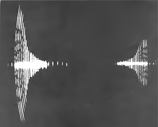
If the grooves, instead of being silent, are modulated, the wiggles in the groove will wiggle the reflected light, so that, instead of a thin strip of light, the reflection will be spread out into a band. This band is the essence of the Buchmann Meyer pattern.
The degree to which the reflected light is spread into a band is dependent on the degree to which the deflection of the groove varies from the gentle curve. In other words, it depends on the maximum gradient of the modulation, so that a low-frequency wiggle will need to have a larger amplitude to create the same band-spreading effect on the reflected light than a high-frequency wiggle (see illustration c). In this way, the dimension of the band-spreading effect is directly proportional to recorded velocity and is practically independent of recorded frequency or the radius of the groove. Herein lies the usefulness of the Buchmann Meyer pattern.
Frequency response
If a series of frequency tones is recorded on the disc, the dimension of the observed Buchmann Meyer bands gives a direct indication of the recorded velocities or, in other words, the frequency response of the cutting head and amplifier. Before the days of feedback cutters and accurate replay phono cartridges, this entirely optical way of discovering what actually was recorded on the disc was crucial to the understanding and development of accurate recording and replay apparatus and very considerable effort went into precision equipment to generate and measure Buchmann Meyer patterns.
Even today, the cutting engineer may use a somewhat simplified version of the Buchmann Meyer technique to determine that the high-frequency response of the cutting equipment is operating correctly.
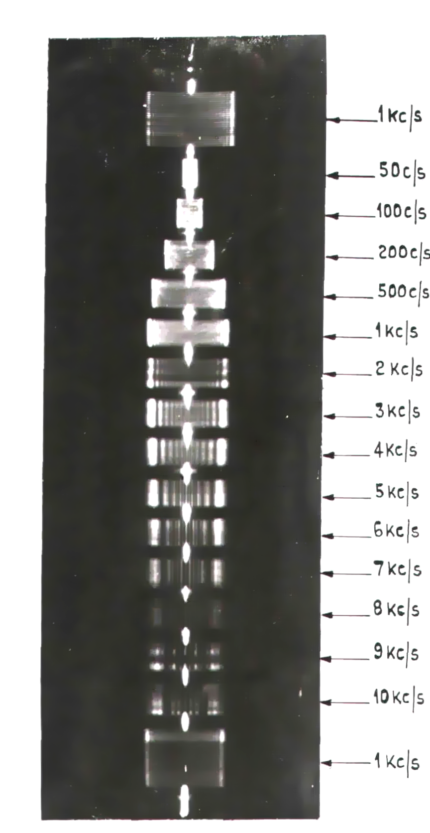
The illustration (right) is of a Buchmann Meyer pattern from a BBC measurement apparatus². That the frequency test record illustrated was recorded constant-velocity above 1kHz and constant-amplitude below is clear from the band amplitudes.
The BBC photograph not only illustrates the use of the pattern, but also reveals one of the shortcomings of the technique due to light interference fringes which break-up the observed bands into vertical sections. Considerable ingenuity was required to make accurate measurements at higher frequencies in spite of these interference effects, many of which are detailed in an article by the BBC team who took the photograph².
The coming of stereo
Buchmann and Meyer's technique was extended to determine other important performance parameters in recording and reproduction such as the magnitude of recording turntable speed fluctuations and the surface noise level of a record³.
However, the coming of stereo created new challenges for the calibration of test records with light patterns4. The illustration (a) above reveals that the pattern is created by the outermost groove-wall which carries the right-channel information in a stereo record. How would one examine the inner groove-wall (which carries the left-hand signal)?
It had been recognised many years earlier that a second pattern is formed under Buchmann Meyer illumination on the near-side of the record surface. In fact, the two patterns are referred to as far-side pattern and the near-side pattern in the literature. The near-side pattern is formed in a very similar way to the far-side pattern as described above, except that the inside groove-wall presents a gently convex reflecting surface, rather than a concave reflector5. Under normal circumstances, the near-side pattern is smaller than the far-side pattern and various mathematical fiddle-factors may be applied to allow for this. Or, under carefully controlled conditions of illumination and observation, the patterns may be equalised. This technique was used in the development of standard stereo test discs4.
References and Notes
1. BUCHMANN, G., and MEYER, E.: "Eine neue optische Messmethode for Grammophonplatten," Elektrische Nachrichten-Technik, 1930, 7, p. 147. A translation of this article appeared in JASA, 12, 303, (1940).
2. The Calibration of Disc Recordings by Light-Pattern Measurements. Axon, P.E and Geddes, W.K.E. Journal of the Audio Engineering Society Volume 5, Number 3, July 1957.
3. Applications of the Buchmann-Meyer Effect in the Calibration of Phonograph Recording and Reproducing Equipment. Cowan, M. and Griffith, P. The Journal of the Acoustical Society of America 11, 380 (1940)
4. Some Aspects of Wear and Calibration of Test Records. Anderson, R. JAES Vol. 9 Number. 2 April 1961
5. The convex surface will not concentrate the incoming light to a point (it will disperse it). But the groove wiggles will still have a similar effect in "band-spreading" the reflected light.

 It has been recognised since the earliest days of disc recording, that if a phonograph record is illuminated with a grazing light so that the beams of incoming light are arranged to reflect off one wall of the v-shaped groove (illustration a), interesting patterns of reflection are observed.
 Buchmann and Meyer's technique was extended to determine other important performance parameters in recording and reproduction such as the magnitude of recording turntable speed fluctuations and the surface noise level of a record³.